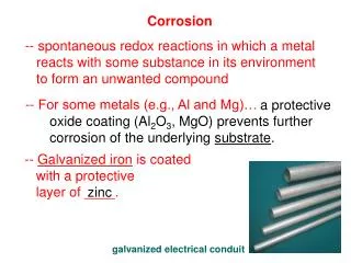
Intergranular Corrosion
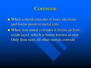
Intergranular Corrosion. Intergranular Corrosion. INTERGRANULAR CORROSION (INTERGRANULAR ATTACK.. IGA ) Metals are usually “polycrystalline” . . . an assemblage of single-crystal grains separated by grain boundaries.

Intergranular Corrosion
E N D
Presentation Transcript
Intergranular Corrosion INTERGRANULAR CORROSION (INTERGRANULAR ATTACK.. IGA) Metals are usually “polycrystalline” . . . an assemblage of single-crystal grains separated by grain boundaries. Grain boundary in a polycrystalline metal (two-dimensional representation).
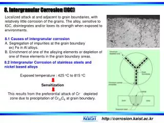
The atoms in the grain boundaries are in a distorted lattice (i.e., disordered). The higher energies of grain boundary atoms make them slightly more reactive than grains. BUT:difference is NOT NOTICEABLE in general corrosion. SOMETIMES . . . grain boundaries can become highly reactive: • by concentration of impurity atoms (e.g., Fe in Al has low solubility in metal, segregates in grain boundaries which corrode more rapidly than grains, and intergranular attack results); • by enrichment of an alloying element (e.g., Zn in brass); • by depletion of an alloying element (e.g., Cr in SS).
IGA (Intergranular Attack) in Austenitic SS (Stainless Steel) What is austenite? The lower-left corner receives prime attention in heat-treating of steels. (In calculations, 0.77 % is commonly rounded to 0.8 %.) Fe-Fe3C Phase Diagram.
Nomenclature • cast iron / CS . . . .> 2%C / < 4% C; • - iron ( - ferritenot to be confused with ferrite oxides).. is BCC • - iron (ferrite) is also BCC; • iron carbide (cementite) is Fe3C, orthorhombic; • - iron (austenite) is FCC. austenite • is non-magnetic; • is unstable below 727C decomposes on slow cooling to ferrite + pearlite if hypoeutectoid; pearlite + eutectic if hyperentectoid (N.B. pearlite is the lamellar mixture of ferrite and carbide that forms on cooling austenite of eutectoid composition . . .0.8% C).
Pearlite. This microstructure is a lamellar mixture of ferrite (lighter matrix) and carbide (darker). Pearlite forms from austenite of eutectoid composition.Therefore, the amount and composition of pearlite are the same as those of eutectoid austenite. Pearlite Formation.Carbon must diffuse from the eutectoid austenite (0.8 percent) to form carbide (6.7 percent).The ferrite that is formed has negligible carbon.
AUSTENITEdecomposes on rapid cooling below 727C (i.e., quenching) to: • MARTENSITE - a metastable forced solution of C in ferrite that is very hard, has BCT (body-centered-tetragonal) structure. • N.B.IN STAINLESS STEELS, THE THREE MAJOR CARBON STEEL PHASES (FERRITE, AUSTENITE, MARTENSITE) CAN ALSO BE FORMED. • Also: ∙ “ferritic-austenitic” (duplex) • ∙ “precipitation-hardened”. • Stability and mechanical/physical properties depend on combination of alloying elements. • austenite stabilizers: C, N, Mn, Ni, (q.v. Ni alloys); • ferrite stabilizers: Si, Cr, Mo, Nb (“Columbium”- Cb), Ti. • Selection of a steel/alloy for a particular application depends on mechanical or physical property considered to be most important.
COMMON STANDARD WROUGHT AUSTENITIC SS COMMON STANDARD WROUGHT FERRITIC SS COMMON STANDARD WROUGHT MARTENSITIC SS
Sensitization: Cr is added to steels to make them “stainless”. The Cr-rich oxide film (based on Cr2O3) is thin, adherent and very protective. BUTif heated into range 510-790C, the steels “sensitize” and become prone toIGA. Sensitization involves the precipitation of Cr carbide (Cr23C6) at the grain boundaries;at the high temperature its solubility is virtually zero. The C diffuses readily, and the disorder in the boundaries provides nucleation sites. This depletes the boundaries of Cr.
Diagrammatic representation of a grain boundary in sensitized type 304 stainless steel. Cross section of area shown above.
Electron photomicrograph of carbides isolated from sensitized type 304 stainless steel.
Sensitization by welding, or “Weld Decay” During welding, the weld “bead” and the metal on either side pass through the temperature range for sensitization. Temperature AND time are crucial for carbide precipitation: sensitized areas are on either side of the bead. Tablecloth analogy of heat flow and temperatures during welding.The rise and fall of each stripe represents the rise and fall of temperature in a welded plate.
Actual measurements made with thermocouples at points ABCD.Fontana says metal at and between points B and C within sensitizing range for some time. Discuss Temperatures during electric-arc welding of type 304 stainless steel..
N.B. Sensitized SS can be used in many environments which are not too aggressive or where selective corrosion not a problem (domestic, architecture) Minimizing IGA of SS (1) Heat Treatment “Quench-Annealing” or ... “Solution-Annealing” or .... “Solution-Quenching” Involves heating to above Cr carbide precipitation temperature to dissolve carbides, then water-quenching to cool through sensitization range rapidly. Most austenitic SS supplied in solution-quenching condition;if welded during fabrication, must be quench-annealed to avoid weld decay during subsequent exposure to corrosive environments. Solution-quenching of large components can be a problem. Discuss:Why not heat-treat just the weld region?
(2) Alloy “Stabilization” Elements that are strong carbide formers are added: Nb (or Nb+Ta)type 347 SS Ti type 327SS Important to ensure that Nb (for example) carbide has precipitated, so that Cr Carbide cannot precipitate and reduce corrosion resistance at grain boundaries (REMEMBER - it is the Crthat provides the corrosion resistance, not the stabilizer). Melting point, F 2250 1450 950 70 C 1230 790 510 20 Schematic chart showing solution and precipitation reactions in types 304 and 347 SS.
Stabilized SS from supplier usually heat-treated by quenching from ~1070C. - Nb carbide has precipitated, - Cr left in solution, hence no C available for any reactions with Cr at lower temperatures. HOWEVER, care is needed during welding etc. If welding involves a rapid cooling of metal from temperatures just at or below the melting point (as can occur in thin sheets), BOTH Nb and Cr remain in solution. This metal can now be sensitized if it is heated to the Cr carbide precipitation range (510 - 790C, as might occur during a stress-relief).
“Knife-Line-Attack” (KLA) may now occur in narrow band next to weld if exposed to corrosive environment. Should have been heat-treated between 790 & 1230 C (Nb carbide precipitates, Cr dissolves). Knife-line attack on type 347 stainless steel.
(3) Use “Low-Carbon” (< 0.03%) Alloy. At concentrations < 0.03%, not enough C can precipitate as Cr carbide to sensitize. Get L-Grade or ELC alloys e.g., “type 304L”. N.B.Must take care to avoid C contamination during casting, welding, etc. Other Alloys and IGA Alloy with precipitated phases may also show IGA: • Duralumin(um) Al-Cu can precipitate CuAl2 and deplete Cu locally; • Die-cast Zn alloys containing Al... IGA in steam, marine environments; • Minor IGA effects in many Al alloys. Elimination of weld decay by type 304ELC. weld bead at back
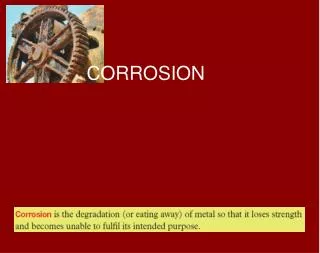
Selective Leaching SELECTIVELEACHING(“Dealloying”,“Parting”) Corrosion in which one constituent of an alloy is preferentially removed, leaving behind an altered (weakened) residual structure. Can occur in several systems.
Combinations of alloys and environments subject to dealloying and elements preferentially removed
Dezincification All Cu-Zn alloys (Brasses) containing> 15% Zn are susceptible . . . e.g. common yellow brass . . . 30 Zn 70 Cu, dezincifies to red copper-rich structure. Dezincification can be uniform... • potable water inside • or plug-type....(boiler water inside, combustion gases outside) Uniform dezincification of brass pipe. Plug-type dezincification.
Overall dimensions of original material tend to be retained . . . residual is spongy and porous . . . often brittle. Can go unnoticed, especially if covered with dirt/deposit, etc. Uniform dezincification... - usually found in high brasses (high[Zn]), acid environments; Plug-type dezincification... - usually found in low brasses, alkaline, neutral or slightly acid environments. Section of one of the plugs shown before
Mechanism (1) Zn atoms leave lattice sites . . . “are leached into the environment selectively’’ Discuss . . . w.r.t.last picture. (2) Generally accepted . . . - brass dissolves; - Zn stays in solution; - Cu re-deposits. Discuss . . . w.r.t.last picture. N.B. possibility for local anode-cathode couples .. Cu deposits accelerate attack. N.B. dezincified areas generally 90-95% Cu; some Cu2O/CuO present if O2 in the environment.
Prevention - Make environment less aggressive (e.g., reduce O2 content); - Cathodically protect; - Use a better alloy (common cure - above not usually feasible)... - “red” brass (<15% Zn) almost immune - Admiralty Brass. . . 70 Cu, 29 Zn, 1 Sn; - arsenical Admiralty. . .70 Cu, 29 Zn, 1 Sn, 0.04 As (Sn and Sn-As in deposited films hinder redeposition of Cu); - For very corrosive environments likely to provoke dezincification, or for critical components, use . . . - cupronickels 70-90 Cu, 30-10 Ni.
“Graphitization” (misnomer . . . graphitization is the breakdown of pearlite to ferrite + C at high temperature) Greycast iron is the cheapest engineering metal . . .2-4% C, 1-3% Si. Hard, brittle, easily cast; carbon present as microscopic flakes of matrix graphite within microstructure. Microstructure of grey cast iron. 100 m
In some environments (notably mild, aqueous soils affecting buried pipe) the Fe leaches out slowly and leaves graphite matrix behind . .appears graphitic . . .soft . . . can be cut with a knife. Pores usually filled with rust. Original dimensions are retained. A 200-mm (8-in.) diameter grey-iron pipe that failed because of graphitic corrosion. The pipe was part of a subterranean fire control system. The external surface of the pipe was covered with soil; the internal surface was covered with water. Severe graphitic corrosion occurred along the bottom external surface where the pipe rested on the soil. The small-diameter piece in the foreground is a grey-iron pump impeller on which the impeller vanes have disintegrated because of graphitic corrosion.
(a)External surface of a grey-ironpipe exhibiting severegraphitic corrosion. (b)Close-up of the graphitically-corrodedregion shown in (a). (c)Micrograph of symmetrical envelopes of graphitically-corroded iron surrounding flakes of graphite. 20 m
Selective Dissolution in Liquid Metals In liquid metal coolants (LMFBR with Na or Na-K coolant), austenitic alloys can lose Ni and Cr and revert to the ferrite phase... Corrosion of Inconel* alloy 706 exposed to liquid sodium for 8,000 hours at 700C (1290F); hot leg circulating system. A porous surface layer has formed with a composition of 95% Fe, 2% Cr and < 1% Ni. The majority of the weight loss encountered can be accounted for by this surface degradation. Total damage depth: 45 m. (a) Light micrograph. (b) SEM of the surface of the porous layer. * Alloy 706 ... 39-44% Ni, 14.5-17.5% Cr, 0.06% C.
Also in fusion-reactor environments (Li as coolant).... Light micrograph of cross-section. SEM of surface showing porous layer. Corrosion of type 316 stainless steel exposed to thermally convective lithium for 7488 hours at the maximum loop temperature of 600C.
Usually, the transport and deposition of leached elements is of more concern than the actual corrosion. (a)(b) SEM micrographs of chromium mass transfer deposits found at the 460C (860C) position in the cold leg of a lithium/type-316-stainless-steel thermal convection loop after 1700 hours. Mass transfer deposits are often a more serious result of corrosion than wall thinning. (a) Cross section of specimen on which chromium was deposited. (b) Top view of surface.
100 m Iron crystals found in a pluggedregion of a failed pump channelof a lithium processing test loop.
Selective Leaching in Molten Salts Molten salts are ionic conductors (like aqueous solutions) and can promote anodic-cathodic electrolytic cells . . . they can be aggressive to metals. ALSO . . . some molten salts (notably fluorides) are “Fluxes” and dissolve surface deposits that would otherwise be protective: dealloying of Cr from Ni-base alloys and stainless steels can occur in the surface layers exposed to molten fluorides; the vacancies in the metal lattice then coalesce to form subsurface voids which agglomerate and grow with increasing time and temperature.
(a)(b) (a) microstructure of type 304L SS exposed to LiF-BeF2-ZrF4-ThF4- UF4 (70-23-5-1-1 mole % respectively) for 5700 hours at 688C. (b) microstructure of type 304L SS exposed to LiF-BeF2-ZrF4-ThF4- UF4 (70-23-5-1-1 mole % respectively)for 5724 hours at 685C.