Welding Processes
Welding Processes. EN358 – Ship Structures. A Brief History of Welding. Late 19 th Century Scientists/engineers apply advances in electricity to heat and/or join metals (Le Chatelier, Joule, etc.) Early 20 th Century


Welding Processes
E N D
Presentation Transcript
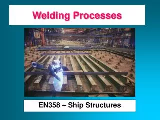
Welding Processes EN358 – Ship Structures
A Brief History of Welding • Late 19th Century • Scientists/engineers apply advances in electricity to heat and/or join metals (Le Chatelier, Joule, etc.) • Early 20th Century • Prior to WWI welding was not trusted as a method to join two metals due to crack issues • 1930’s and 40’s • Industrial welding gains acceptance and is used extensively in the war effort to build tanks, aircraft, ships, etc. • Modern Welding • the nuclear/space age helps bring welding from an art to a science
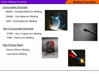
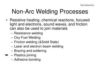
Types of Welding Fusion Welding Pressure Welding Friction Welding Homogeneous Heterogeneous Brazing Soldering Gas Welding Electroslag MIG TIG High Energy Beam Shielded Metal Arc – “Stick” Electric Arc
Weldability of a Metal • Metallurgical Capacity • Parent metal will join with the weld metal without formation of deleterious constituents or alloys • Mechanical Soundness • Joint will be free from discontinuities, gas porosity, shrinkage, slag, or cracks • Serviceability • Weld is able to perform under varying conditions or service (e.g., extreme temperatures, corrosive environments, fatigue, high pressures, etc.)
Fusion Welding Principles • Base metal is melted • Filler metal may be added • Heat is supplied by various means • Oxyacetylene gas • Electric Arc • Plasma Arc • Laser
Fusion Welding ELECTRODE COATING CORE WIRE WELDING ATMOSPHERE ARC STREAM ARC POOL SOLIDIFIED SLAG PENETRATION DEPTH WELD BASE METAL
Weld Metal Protection • During fusion welding, the molten metal in the weld “puddle” is susceptible to oxidation • Must protect weld puddle (arc pool) from the atmosphere • Methods • Weld Fluxes • Inert Gases • Vacuum
Weld Fluxes • Typical fluxes • SiO2, TiO2, FeO, MgO, Al2O3 • Produces a gaseous shield to prevent contamination • Act as scavengers to reduce oxides • Add alloying elements to the weld • Influence shape of weld bead during solidification
Inert Gases • Argon, helium, nitrogen, and carbon dioxide • Form a protective envelope around the weld area • Used in • MIG • TIG • Shield Metal Arc
Vacuum • Produce high-quality welds • Used in electron beam welding • Nuclear/special metal applications • Zr, Hf, Ti • Reduces impurities by a factor of 20 versus other methods • Expensive and time-consuming
Types of Fusion Welding • Oxyacetylene Cutting/Welding • Shielded Metal Arc (“Stick”) • Metal Inert Gas (MIG) • Tungsten Inert Gas (TIG)
Oxyacetylene Welding • Flame formed by burning a mix of acetylene (C2H2) and oxygen • Fusion of metal is achieved by passing the inner cone of the flame over the metal • Oxyacetylene can also be used for cutting metals TORCH TIP 2300 deg F Inner Cone: 5000-6300 deg F Combustion Envelope 3800 deg F
Shielded Metal Arc (Stick) • An electric arc is generated between a coated electrode and the parent metal • The coated electrode carries the electric current to form the arc, produces a gas to control the atmosphere and provides filler metal for the weld bead • Electric current may be AC or DC. If the current is DC, the polarity will affect the weld size and application
Shielded Metal Arc (con’t) • Process: • Intense heat at the arc melts the tip of the electrode • Tiny drops of metal enter the arc stream and are deposited on the parent metal • As molten metal is deposited, a slag forms over the bead which serves as an insulation against air contaminants during cooling • After a weld ‘pass’ is allowed the cool, the oxide layer is removed by a chipping hammer and then cleaned with a wirebrush before the next pass.
Inert Gas Welding • For materials such as Al or Ti which quickly form oxide layers, a method to place an inert atmosphere around the weld puddle had to be developed
Metal Inert Gas (MIG) • Uses a consumable electrode (filler wire made of the base metal) • Inert gas is typically Argon DRIVE WHEELS CONSUMABLE ELECTRODE POWER SOURCE SHIELDING GAS ARC COLUMN BASE METAL PUDDLE
Tungsten Inert Gas (MIG) • Tungsten electrode acts as a cathode • A plasma is produced between the tungsten cathode and the base metal which heats the base metal to its melting point • Filler metal can be added to the weld pool TUNGSTEN ELECTRODE (CATHODE) POWER SOURCE TUNGSTEN ELECTRODE + + + + - - - SHIELDING GAS ARC COLUMN BASE METAL PUDDLE BASE METAL (ANODE)
Welding Positions INCREASING DIFFICULTY FLAT HORIZONTAL OVERHEAD VERTICAL
Weld Defects • Undercuts/Overlaps • Grain Growth • A wide T will exist between base metal and HAZ. Preheating and cooling methods will affect the brittleness of the metal in this region • Blowholes • Are cavities caused by gas entrapment during the solidification of the weld puddle. Prevented by proper weld technique (even temperature and speed)
Weld Defects • Inclusions • Impurities or foreign substances which are forced into the weld puddle during the welding process. Has the same effect as a crack. Prevented by proper technique/cleanliness. • Segregation • Condition where some regions of the metal are enriched with an alloy ingredient and others aren’t. Can be prevented by proper heat treatment and cooling. • Porosity • The formation of tiny pinholes generated by atmospheric contamination. Prevented by keeping a protective shield over the molten weld puddle.
Residual Stresses • Rapid heating and cooling results in thermal stresses detrimental to joint strength. • Prevention • Edge Preparation/Alignment – beveled edges and space between components to allow movement • Control of heat input – skip or intermittent weld technique • Preheating – reduces expansion/contraction forces (alloys) and removes moisture from the surface • Peening – help metal stretch as it cools by hitting with a hammer. Use with care since it may work harden the metal • Heat Treatment – “soak” the metal at a high temperature to relieve stresses • Jigs and Fixtures – prevent distortion by holding metal fixed • Number of Passes – the fewer the better.
Joint Design BUTT JOINT FILLET JOINT STRAP JOINT CORNER JOINT LAP JOINT
Generalized Welding Symbol FAR SIDE DETAILS Field weld symbol Weld Geometry D L1-L2 Electrode Material Weld all-around for pipes, etc. L1-L2 D ARROW SIDE DETAILS D = Weld Depth (usually equal to plate thickness) L1 = Weld Length L2 = Distance between centers for stitched welds The Field Weld Symbol is a guide for installation. Shipyards normally do not use it, except in modular construction.
Example Welding Symbol Geometry symbol for V-groove One-sided welds are max 80% efficient Two sided are 100% efficient 1/2 1/2 1/2” 1/2”
Weld Symbols (Butt Joints) Backing