Power Lines
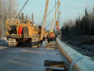
Power Lines. The power transmission line is one of the major components of an electric power system. Its major function is to transport electric energy, with minimal losses, from the power sources to the load centers, usually separated by long distances. The design of a

Power Lines
E N D
Presentation Transcript
Power Lines The power transmission line is one of the major components of an electric power system. Its major function is to transport electric energy, with minimal losses, from the power sources to the load centers, usually separated by long distances. The design of a transmission line depends on four electrical parameters: 1. Series resistance2. Series inductance3. Shunt capacitance4. Shunt conductance
Parameters of Power Lines Resistance: The resistance increases along the temperature, as the temperature is bound to increase with the increase of currant carried by the line. Rt = R0 (1+0) Where: Rt is Resistance at temperature t R0 is resistance at 00 C 0 is temperature coefficient • Where : • R is series resistance • is a resistivity of material used L is length of the line A is a x-sectional area of the line. And for uniform cable this is defined in per unit length: R = /A
Power Line Parameters..Inductance • A current-carrying conductor produces concentric magnetic flux lines around the conductor. If the current varies with the time, the magnetic flux changes and a voltage is induced. Therefore, an inductance is present, defined as the ratio of the magnetic flux linkage and the current. The magnetic flux produced by the current in transmission line conductors produces a total inductance whose magnitude depends on the line configuration. To determine the inductance of the line, it is necessary to calculate, as in any magnetic circuit with permeability , the following factor : • 1.Magnetic field intensity H • 2.Magnetic field density B • 3. Flux linkage
Power Line Parameters Inductance: The value of inductances varies due to type of transmission lines; • Two parallel lines or • Coaxial line Outer Flux Inner Flux
Internal Inductance Due to Internal Magnetic Flux To obtain the internal inductance, a magnetic field with radius x inside the conductor of length l is chosen, as shown in: Ampere’s law determines the magnetic field intensity Hx, constant at any point along the circle contour as: Ix Hx r dx L Length
Inductance due to Internal Flux The magnetic flux density Bxis obtained: For nonmagnetic material =0 = 4x10⁻⁷
External Inductance The external inductance is evaluated assuming that the total current I is concentrated at the conductor surface (maximum skin effect). At any point on an external magnetic field circle of radius y (Fig.),the magnetic field intensity Hyand the magnetic field density By, per unit length, are: y r D1 D2 dy
Two Wire System The system have two wires carrying current in reverse direction. External flux of each is interacting with other internal of the other cable. The effective Flux and therefore inductance is super positioned of both. D
Total Flux & Inductance Where GMR is geometric Mean Radius
Example No 1 Find the loop inductance per km of a single phase overhead lie consisting of two conductors, each 1.213 cm diameter. The spacing between conductors is 1.25 m and frequency is 50 Hz.
Solution No 1 r= 1.213/2 = 0.6065 cm r’= 0.7788 x0.6065= 0.4723 cm L= 4x10⁻⁷Ln (125/0.4723) = 22.31x10⁻⁷ H/m or 22.31x 10⁻⁴ H/km X= 2..f.L= 2..50.22.31x10-4 Ohms/km = 0.7 /km
Types of Line Conductors • There are two types of transmission line conductors: overhead and underground. Overhead conductors, made of naked metal and suspended on insulators, are preferred over underground conductors because of the lower cost and easy maintenance. Also, overhead transmission lines use aluminum conductors, because of the lower cost and lighter weight compared to copper conductors, although more cross-section area is needed to conduct the same amount of current. There are different types of commercially available aluminum conductors: aluminum-conductor-steel-reinforced (ACSR), aluminum-conductor-alloy-reinforced (ACAR), all-aluminum-conductor (AAC), and all-aluminum-alloy-conductor (AAAC
Multiple Strand LINE ACSR is one of the most used conductors in transmission lines. It consists of alternate layers of stranded conductors, spiraled in opposite directions to hold the strands together, surrounding a core of steel strands. Figure shows an example of aluminum and steel strands combination.
Types of Line Conductors The purpose of introducing a steel core inside the stranded aluminum conductors is to obtain a high strength-to-weight ratio. A stranded conductor offers more flexibility and easier to manufacture than a solid large conductor. However, the total resistance is increased because the outside strands are larger than the inside strands on account of the spiraling [8]. The resistance of each wound conductor at any layer, per unit length, is based on its total length as follows