Download
1 / 22
220 likes | 248 Vues
Learn about the LHCf experiment, cosmic ray physics, detector's location, discrimination models, and performance evaluation through simulation and SPS beam tests. The collaboration aims to confirm various interaction models crucial for cosmic ray studies. The LHCf detectors, positioned 140m from the Interaction Point, feature two arms covering a high pseudo-rapidity range, each with specific design specifications for tracking and energy measurements. Discover how the detectors aid in gamma spectrum modeling, position, and energy resolutions for better cosmic ray analysis. Stay informed on the exciting advancements in cosmic ray research!

E N D
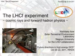
The LHCf detectors: zero degree calorimeters at LHC for cosmic ray physics Tsuyoshi Mase for the LHCf collaboration Solar-Terrestrial Environment Laboratory, Nagoya University
Outline • Motivation of the LHCf experiment • High energy cosmic ray problem • hadron interaction model • LHCf detector • Location • Discrimination the hadron interaction models • Design • Performance (SPS beam test and simulation) • Conclusion TIPP09 T.Mase
Energy spectrum of cosmic rays Knee; acceleration limit of galactic CRs? GZK cutoff; Propagation limit due to CMB Engel, Nuclear Phys. B (Proc. Suppl.) 151 (2006) 437-461 TIPP09 T.Mase
Cosmic ray composition by Auger Xmax favors heavy primary interpretation strongly depends on the hadron interaction model Confirmation of the various models using the LHC is important key for the cosmic ray physics. Anisotropy favors light primary (if accept AGN correlation) TIPP09 T.Mase
CMS / TOTEM LHC accelerator ALICE LHCb ATLAS / LHCf The 14TeV center of momentum energy of the LHC will push the laboratory equivalent collision energy up to 10^17eV. TIPP09 T.Mase
The LHCf collaborator K.Fukui, Y.Itow, T.Mase, K.Masuda, Y.Matsubara, H.Menjo, T.Sako, K.Taki Solar-Terrestrial Environment Laboratory, Nagoya University, Japan K.YoshidaShibaura Institute of Technology, Japan K.Kasahara, M.Mizuishi, S.Torii Waseda University, Japan T.TamuraKanagawa University, Japan Y.MurakiKonan University Y.ShimizuICRC, University of Tokyo, Japan M.HaguenauerEcole Polytechnique, France W.C.TurnerLBNL, Berkeley, USA O.Adriani, L.Bonechi, M.Bongi, R.D’Alessandro, M.Grandi, P.Papini, S.Ricciarini, G.Castellini, A. Viciani INFN, Univ. di Firenze, Italy A.TricomiINFN, Univ. di Catania, Italy J.Velasco, A.Faus IFIC, Centro Mixto CSIC-UVEG, Spain D.Macina, A-L.PerrotCERN, Switzerland TIPP09 T.Mase
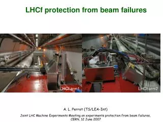
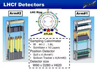
Location of LHCf Arm1 Arm2 90cm I.P. 140m 140m LHCf Detectors installed in the TAN region, 140m away from theInteraction Point. Both side of I.P. (Arm1 and Arm2) LHCf covers pseudo-rapidity > 8.4 neutral particle absorber TIPP09 T.Mase
Model dependence in LHCf Gamma Spectrum Model Discrimination by Gamma, Neutron and p0 expected spectra using some hadron interaction models TIPP09 T.Mase
LHCf Detector1 (Arm1) Impact point 2towers 24 cm long stacked vertically with 5 mm gap Lower: 2 cm x 2 cm area Upper: 4 cm x 4 cm area 4 pairs of scintillating fiber layers for tracking purpose (6, 10, 32, 38 r.l.) Absorber 22 tungsten layers 7mm – 14 mm thick (W: X0 = 3.5mm, RM = 9mm) 44 radiation length 1.7 interaction length 16 scintillator layers (3 mm thick) Trigger and energy profile measurements Energy TIPP09 T.Mase
LHCf Detector2 (Arm2) We used LHC style electronics and readout Impact point 2 towers 24 cm long stacked on their edges and offset from one another Lower: 2.5 cm x 2.5 cm Upper: 3.2 cm x 3.2 cm 4 pairs of silicon microstrip layers (6, 12, 30, 42 r.l.) for tracking purpose (X and Y directions) 16 scintillator layers (3 mm thick) Trigger and energy profile measurements Absorber 22 tungsten layers 7mm – 14 mm thick (2-4 r.l.) (W: X0 = 3.5mm, RM = 9mm) Energy TIPP09 T.Mase
Double arm detectors 90mm 290mm Arm#2 Detector Arm#1 Detector TIPP09 T.Mase
Compact calorimeter and shower leakage correction • Compact two tower calorimeter • need for science • fit the limit of TAN • avoid multi-hit • reconstruct p0 invariant mass • The p0 mass can be reconstructed in the invariant mass distribution of two gamma -rays, one each hitting the two tower calorimeters of Arm1 or Arm2. • Shower leakage occurs • The fraction of shower leakage is only a function of the position and independent of the energy TIPP09 T.Mase
SPS beam test • 2007 Aug. 24 - Sep.11 • Aim for SPS beam test Calibration the performance • Energy Calibration • Energy Resolution • Position Resolution • particle ID electron 50, 100, 150, 180, 200GeV/c muon 150GeV/c proton 150, 350GeV/c LHCf Detector LHCf Detector ADAMO (silicon tracker) Trigger scintillator Beam Pipe Silicon Tracker TIPP09 T.Mase
Energy Resolution Summing up the signal in all the layers, the energy resolution is defined as root-mean-square of the distribution. SPS beam test result and simulation Simulation at the LHC condition L.G. = Low PMT Gain H.G. = High PMT Gain TIPP09 T.Mase
Position Resolution (SciFi : Arm1) 200 GeV electrons SPS beam test result The center determined by the SciFi is compared with the incident particle position estimated by ADAMO. Simulation at the LHC condition TIPP09 T.Mase
Position Resolution (Silicon : Arm2) SPS beam test result This analysis was done using ADAMO for the reconstructionof the trajectory of each particle hitting the calorimeter. 200 GeV electrons • 64mm x 64mm total surface area • 285mm thick n-type wafer • A sequence of 768 p+ microstrips with 80mm pitch TIPP09 T.Mase
40mm 20mm p0 reconstruction (1) Calorimeters Shower Profile @ First SciFi Layer Egamma=46GeV Y X Egamma=18GeV Y X 350 GeV Proton beam Not in scale! gamma Carbon target (3 cm) in the slot used for beam monitor 9.15 m Arm1 TIPP09 T.Mase
p0 reconstruction (2) 250 p0 events triggered (in a quite big background) The background is caused by uncorrelated pairs those accidentallyhit the two calorimeters simultaneously. The background distribution was evaluated by shifting theevents in the two calorimeters so that any correlated pairs disappear. TIPP09 T.Mase
Radiation test • The LHCf detectors will be exposed to a considerable amount of ionizing radiation • Using 290MeV/n Carbon beam and 100TBq 60Co gamma ray 100Gy TIPP09 T.Mase
LHCf Operation 100Gy • LHCf operation • Luminosity < 1030 cm-2 s-1 • 107 inelastic collision • 3 days operation • The decrease of the light output is not large for doses of interest for LHCf • The laser calibration system can correct • The manipulators move the detectors to the safe position TIPP09 T.Mase
Conclusion • LHCf will set a crucial calibration point at 1017eV for the hadron interaction models • The LHCf detectors are sampling and imaging calorimeters • locate both side of the IP1 (Arm1 and Arm2) • made of plastic scintillators interleaved with tungsten converters • correct the shower leakage from the calorimeter • Performance was evaluated by SPS and simulation • energy resolution is 5% above 100GeV gamma-ray • position resolution is 150um@Arm1, 50um@Arm2 • reconstruct p0 mass • Radiation damage is negligible TIPP09 T.Mase