Download
1 / 10
120 likes | 372 Vues
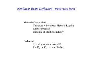
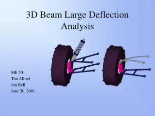
3D Beam Large Deflection Analysis. ME 501 Tim Allred Jon Bell June 20, 2001. Overview. Objective Problem Definition Analysis Results What we learned Conclusion. Project Objective. Model this mechanism in 3D Compare deflection and stress results using large deflection analysis to:

E N D
3D Beam Large Deflection Analysis ME 501 Tim Allred Jon Bell June 20, 2001
Overview • Objective • Problem Definition • Analysis • Results • What we learned • Conclusion
Project Objective • Model this mechanism in 3D • Compare deflection and stress results using large deflection analysis to: • Approximate 2D pseudo rigid body model • 2D beam model • 3D beam model using small deflection analysis
Original Suspension Compliant Suspension 16 Material: Carbon/Epoxy Composite SUT: 330 ksi E: 20.6 Mpsi 6.5 14.6 500 lbs. Cross-Sectional Shape 2.0 X 0.215 in. Designed for 8 inches of vertical motion for 500 lb force input. Problem Definition
3D beam large deflection 8 5 4 1 7 6 9 3 2 5 4 1 6 7 3 2 Analysis Models • 2D beam large deflection • 3D beam small deflection
3D w/ large displacements 3D w/ small displacements 2D model Psuedo-rigid body results Displacement at node 7 9.7 inches 7.4 inches 8.6 inches 8 inches Maximum Stress 182 ksi 171 ksi 177 ksi N/A Results
3D large displacement model 2D model 3D small displacement model Displacements 8.6 “ 9.7 “ 7.4 “
3D large displacement model 2D model 3D small displacement model Stresses Stress distributions change Stressmax=182 ksi Stressmax=177 ksi Stressmax=171 ksi
MR What we learned about ANSYS! • 2 Plane Bending • 3D beam Torsional Moment of Inertia • With no input, ANSYS automatically inserts polar moment of inertia or Ixx +Iyy • Maximum Stress includes only Bending + Axial Stresses • Shear Stress due to Torsion not included • For correct failure analysis, user would need to calculate shear stress by hand
Conclusions • 3D modeling with large displacement is necessary for accurate results on this particular problem due to the torsion introduced on the compliant member • ANSYS is very useful in predicting results and learning about the important parameters of the problem • Prototype would need to be built for accurate verification of results