Use Cases - Requirements UML Style
610 likes | 801 Vues
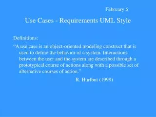
February 6. Use Cases - Requirements UML Style. Definitions:

Use Cases - Requirements UML Style
E N D
Presentation Transcript
February 6 Use Cases - Requirements UML Style Definitions: “A use case is an object-oriented modeling construct that is used to define the behavior of a system. Interactions between the user and the system are described through a prototypical course of actions along with a possible set of alternative courses of action.” R. Hurlbut (1999)
“Use cases are what happens when actors interact with the system. An actor uses the system to achieve a desired goal. By recording all the ways our system is used we accumulate all the goals or requirements of our system…The collection of use cases should define all system behavior relevant to the actors to assure them that their goals will be carried out properly.” Alistair Cockburn “Creating a reasonably exhaustive set of use cases is the single best insurance you can buy to ensure that you are building the system the customer needs.” Jesse Liberety (1998)
Use cases do not say anything about the internal workings of the system. They just tell you how the users interact with the system and how it responds. Finding use cases To build use cases you must have the active participation of your customers. As in traditional requirements gathering, you must interview the users and help the user articulate how he uses the system. Domain experts are another important source of use cases.
It is difficult to know when you have all the use cases. Having a rapid prototype available can be very helpful in understanding all the ways in which the system will be used. Actors Actors are not part of the system. They are anyone or anything that must interact with the system. To help identify them you can ask: Who benefits from the system? Who will supply information or take information from the system? Who supports and maintains the system?
For each actor, the results they require of the system constitute use cases. For example, Liberty (1998) talks about the customer of a video rental store may find a movie to rent, rent a tape, return a tape, and reserve a tape. Resulting use cases would include: 1. The customer rents a tape 2. The customer returns a tape 3. The customer browses the system looking for a tape to rent 4. The customer reserves a tape for later viewing Use cases are thus the functionality provided to an actor by the system.
Attributes and use cases When you look at the attributes of things in your problem domain you may come up with more use cases. For example, in the video store movies have names, actors, ratings, release dates, etc. These attributes can relate to ways actors will interact with the system. For example, customers may want movies made before some date, starring a particular actor, or carrying a particular rating. Naming use cases Once you have developed a sufficient number of use cases each should be given a unique name.
Flows of events for use cases Each use case is described in terms of the events needed to accomplish the end state of the use case. This can include how the use case starts and ends, what data the use case requires, and the normal sequence of events in the use case. Use case diagrams Use cases can be represented diagrammatically to represent several related use cases. The actor is represented by a stick figure. A line between the actor and a use case (represented by an oval) indicates that the actor is associated with or communicates with the use case.
Use case relationships Two types of relationships between use cases are described - uses and extends. When one use case <<uses>> another use case it uses the functionality of the other use case. The extends relationship indicates that behavior that is optional or occurs only under certain conditions. Scenarios Scenarios are specific series of events illustrating “typical” instances of a use case. Scenarios are helpful in revealing relationships between actors and the flow of events in your system.
The role of use cases The use case model is about describing what our system will do at a high level and with a user focus for the purpose of scoping the project and giving the application some structure. Use cases are an informal and imprecise modeling technique. Use cases are not intended to capture all of the system requirements. Kenworthy (1997) Yet I. Jacobson writes that OO software engineering is “a use case driven approach.”
Timothy Korson (2000) reported an experience working with a large software project which caused him to consider the proper role of use cases. This project had more than 1,000 developers working on it. Development teams were called upon to send in their use cases. A total of 12, 386 use cases were submitted. The use cases were not very useful. They were seen as too detailed and sometimes in error. Korson suggests that use cases be organized hierarchically. Such an organization is needed to manage the complexity of the typical set of requirements. Korson suggests that the top level requirements for a system should be expressed in no more than a dozen or so use cases.
Korson (2000) is also concerned that use cases have led to insufficient abstraction in the formulation of requirements. Too often use cases jump right into interface specification issues. “Unless the first level of requirements is interface neutral, clients are robbed of the natural opportunity to consider other alternatives and designers are not prompted to build extensibility into the system…For example when it is explicit that “deposit coin” is simply an interface binding to the requirement of “accept payment,” then software designers, hardware engineers, marketing personnel, product managers, et. al. are prompted to consider the possibilities and implications of other interface bindings such as an electronic cash or credit card reader.”
Thus, use cases may tend to be formulated too concretely and at too detailed a level to encourage creativity and flexibility in design. Korson makes the point that domain knowledge is important for software developers. He sees a profusion of use cases as a symptom of insufficient domain knowledge among the programmers.
Use cases are only as good as is the actor’s perspective upon which they are based. “Identifying a complete set of actor roles means that I will capture all of the user’s viewpoints, but what if some of the actors don’t really understand the true business needs? What if the development team misunderstands the use cases?” Domain knowledge is seen as crucial in creating use cases. “You can’t create correct, useful use cases if you don’t understand the domain. This is as true for the client as for the development team. Never assume the client can articulate business needs. Typically each actor and domain expert has a very limited view of the domain in which an application will live.”
It is difficult to implement use cases correctly without good understanding of the domain. Korson cites a scientist who worked with radar signal processing who needed software developed for this area. He stated it was easier to teach a radar specialist how to program than to teach a programmer about radar. Korson, in working on a large accounting software project found that without good understanding of accounting concepts, a software engineer will misinterpret even well written use cases. For example,the word journal has several different meanings to accountants.
Specification Phase The specification of a software project serves as both a statement of the agreement between the development team and the client over what is to be built and a communication to the design team so they can use it to draw up the design. It can be difficult to make the same document clear and intelligible to both the client and the design team. The specification document is a contract between the client and the developer. It specifies exactly what the product must do and the constraints on the product. The specification document may consist of page after page of description.
The purpose of the specification document is to provide a complete and detailed description of the functional capabilities of the software being developed. It is more detailed than the requirements document. It informs both the client and the design and implementation teams what the software will actually do to satisfy the requirements. Specifications documents include the software functions, including such details as formulas for converting input to output and sequences of operations. Interfaces (if any) between client and server applications are detailed. The user interface is described. General constraints on hardware, users, and development software are spelled out.
It has been pointed out that specifications written in plain English tend to have contradictions, ambiguities, and omissions. The experiences following the publications of a paper by Naur on the specifications of a system for text-processing. A year later a reviewer published a paper illustrating one fault in Naur’s paper. Another year later another paper detected three more faults. A subsequent paper added three more faults. The third critique revised the original specifications, making them four times as large as they were originally.
In 1985 a paper came out which detected 12 faults in the revised specifications. They revised the specifications again. Another author has pointed out a fault in them. A key point is that all these specifications were for a small 25-30 line program and they were constructed by experts with as much time as they needed. What chance, then, does an ordinary computer professional, working under a time deadline have of producing error-free specifications?
Another example of the problem with ordinary English is illustrated by Lejk and Deeks (1998) with the following example: A product is passed as fit for sale if it passes a mechanical test and an electrical test and has the correct dimensions. If it fails the mechanical test or the electrical test (but not both), it is sent back to the workshop for repair. In all other cases, the product is rejected. This may, at first sight, seem like a reasonable description of a quality control process. But it contains an error.
According to a literal reading of the policy, a product which has incorrect dimensions and has failed the electrical test would be sent back to the workshop for repair simply because it passed the mechanical test. The writer meant to say that a product must have the correct dimensions even to be considered as fit for sale. Because “and has the correct dimensions” is the end of the first sentence, the writer (and many readers) have assumed that this condition carries across to the start of the second sentence. Inconsistencies and inaccuracies are easily hidden in the words of ordinary English. Creating a more accurate description can lead to a lengthy narrative.
Need for graphical models Because it is so difficult to represent all that a software system is to do with words many attempts have been made to develop graphical means of representing software specifications so that they can be carried into the design and implementation phases. Established engineering disciplines have sets of unambiguous representations for modeling products. They have tools such as block and schematic diagrams and blueprints.
Software engineering has no equivalents - there are many different notations and disagreement about which modeling primitives and notations to use. Many times software developers will implement systems without producing analysis and design models. Yet it is difficult to easily go back and forth between the problem and the implementation unless the problem is relatively small.
“The cognitive leap from understanding a problem to implementing a system is too great to proceed without including analysis and design models as key deliverables in the development process...Omitting these analysis and design activities or doing an incomplete job on them is widely recognized as a principal cause of development errors, high maintenance costs,and failure to build systems that meet user requirements. Without usable and precise requirements specifications and design models, acceptance testing and quality assurance become nearly impossible, and documentation will likely be inaccurate.” Anthony Wasserman (1996)
Stepwise Refinement Stepwise refinement is a problem-solving technique that underlies many specification, design, and implementation techniques. Stepwise refinement is important because with large systems it is impossible for developers to focus on all aspects of the system design at once. Stepwise refinement prioritizes the problems to be solved, breaking down a stage into manageable chunks. Other aspects are postponed until later.
“The power of stepwise refinement is that it helps the software engineer to concentrate on the relevant aspects of the current development phase and to ignore details that, although essential in the overall scheme, need not be considered, and in fact should be ignored, until later. Unlike a divide-and-conquer technique in which the problem is decomposed into pieces that are essentially of equal importance, in stepwise refinement the importance of a particular aspect of the problem changes from refinement to refinement. Initially, a particular issue may be irrelevant, but later that same issue will be of critical importance.” Stephen Schach (1999)
Schach (1999) presents an example of stepwise refinement. It involves updating a sequential master file of the subscribers to a magazine. A software program to manage the file would support such operations as INSERT, MODIFY, and DELETE entries into the file. Transaction types are: Type 1: INSERT (add a new subscriber) Type 2: MODIFY (change existing subscriber record) Type 3: DELETE (drop an existing subscriber record) A first step might be to diagram an overall view of the problem.
The first refinement decomposes the update master file box into three boxes - INPUT, PROCESS< and OUTPUT.
We will then assume we can produce the correct record at the right time and write the correct record to the correct file at the right time. We concentrate on the PROCESS. If current transaction file record comes after the current old master file record, the old master file record is written to the new master file. If the current transaction file record comes before the current old master file record, there may be (only) an insertion operation into the new master file. If the current transaction file record are equal, there may be a modification or a deletion of the master file record.
Now that we have worked to understand PROCESS better, we can produce the second refinement shown on the next slide. How to handle input and output have been deferred to a later refinement. Similarly, how to handle the end-of-file condition and what to do when an error condition is encountered are deferred. With stepwise refinement solving such problems can be postponed until a later refinement. Stepwise refinement allows us to work within human information processing limitations which restrict how much we can process at one time.
Structured Analysis and the Data Flow Diagram “Structured analysis is the use of graphic documentation tools to produce a new kind of functional specification - a structured specification. The primary documentation tools of structured analysis are • data flow diagram (DFD) • data dictionary • structured English Data flow diagrams provide an easy, graphical means of modeling the flow of data through a system…A typical system requires several levels of data flow diagrams.” Yourdon (1979)
Schach (1999) presents an example of the use of the DFD to model software to be used in a shop that purchases software from suppliers and sells it to the public. The DFD is used to model the logical flow of information as opposed to the physical data flow. That is, it focuses on what happens as opposed to how it happens. The following DFD could correspond to either a totally manual implementation or to a computerized implementation.
A flow of data is shown by a line with an arrowhead, indicating the direction of flow. Each flow of data has a label to explain what it is. A source or destination of data is indicated by a double square. It is located outside the system. A process transforms the flow of data. It is the only part of the DFD that shows something happening. It makes the data flow.The description within the process must start with an imperative verb. A store of data within the system is represented by an open-ended rectangle.
With larger systems it becomes impractical to have just one DFD. Stepwise refinement is done to parts of a DFD, creating a hierarchy of DFD’s. That is, a single shape at one level is expanded to a complete DFD at a lower level. It is recommended that when creating DFD’s it is best to first concentrate on the processes, then identify the stores of data and sources or destinations of data, and finally add the flows of data. A stepwise refinement of the initial DFD is presented next.
A portion of the third refinement of the DFD is presented in the next slide. Sections relating to accounts payable and software suppliers are left out due to the increasing size of the DFD. Some recommend that the DFD’s assume a prominent place in the specifications document as a clear representation of the logical flow of data in the system. Others suggest they be relegated to an appendix.
Some believe that no control information should be included in a DFD. There is a strong implication that all of the processes shown in the process shapes could be taking place at the same time. Most believe that no control information should be shown in a data flow diagram. For example, in the previous DFD once an order is verified as valid the details of the package to be ordered can be sent to the PENDING ORDERS data store OR the details of the package on hand can be sent to the assemble orders process.
Weinberg (1980) suggests that we should ignore data flow control considerations when developing overview DFD’s. However, he suggests that we perhaps should include details of data-flow control on lower-level, more detailed diagrams. He proposes a notation for clarifying the association of flows of data: * denotes a logical AND connection denotes an exclusive OR connection denotes an inclusive OR connection
Once we have used stepwise refinement to get to the bottom level of a DFD there is still a need to write about what exactly goes on in this bottom level. Decisions may be made or operations repeated. These need to be described in ways that are accurate, unambiguous, precise, and complete. Such process descriptions are contained in elementary process descriptions (EPD’s), and there are several ways of writing these. They can be done using pseudocode, structured English, decision trees, or decision tables.
Structured English has no hard and fast definition. It is an attempt to remove the background noise words from narrative descriptions. Pseudocode is a more formal variation of structured English. Decision trees make it easy to check that all possibilities have been taken into account. This may be especially helpful in complex cases. Decision Tables are useful when a combination of decisions have to be made in order to establish a result. Decision tables are made up of four quadrants.
In limited entry decision tables conditions are entered into the table as direct questions to which the answer can only be yes (Y) or no (N). All the possible combinations of Y’s and N’s are placed in the condition entry quadrant of the table and each vertical set of Y’s and N’s taken together is called a rule. The possible results or actions are placed in the action stub and the relevant action(s) resulting from each rule are marked in the action entry quadrant with an ‘X’. Lejk and Deeks (1998) Note on the following table that unnecessary (redundant) conditions may be eliminated by inserting a ‘-’ entry.
The data dictionary is an important part of a DFD. It goes along with our goal to have a precise definition of all terms included in our system specification. Definitions are entered into data dictionaries in a quasi mathematical form called extended BNF (Backus-Naur format). Every data flow and store of data has a corresponding data entry. For example, a “Customers” data store might have the following hierarchy of entries: Character = [‘a’…’z’ | ’A’…’Z’ | ‘-’ | ’.’ | ‘ ‘ ] Name = {Character}30 Customer = [ Name + Address + Phone_Number ] Customers = {Customer}