Download

1 / 39
390 likes | 431 Vues
The UPDM specification submission to the DoDAF WG covers the background, approach, and highlights of the UPDM development process. It details the Object Management Group's role, timeline, and necessary submission documents, emphasizing the methodology agnostic nature, system functionality descriptions, and operational concepts. Learn about the role of domain metamodel, UML profile, and the benefits of a model-based approach for designing UPDM.

E N D
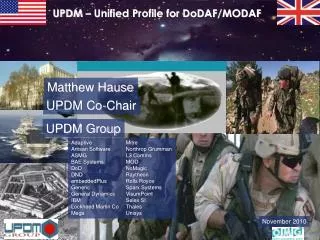
UPDM – UML profile for DoDAF and MODAF Briefing to the DoDAF WG
Introduction to the UPDM specification submission • Background • Approach • Highlights • Deep dive if requested
Background – The Object Management Group (OMG) • OMG is an international industry consortium that produces industry standards using a rigorous technology adoption process • UML, SysML, MDA™, etc. • UPDM Requirements derived from DoDAF and MODAF requirements • UPDM development included broad industry participation from tool vendors and end users, as well as DoD/MOD inputs to requirements • UPDM supports current DoDAF/MODAF requirements and can evolve to meet future needs • Can produce standard DoDAF products • Leverages cross industry standards based approaches (e.g., MDA™ ,UML, SysML) to enhance tool and architecture data interoperability • MDA™ foundation enables UPDM to evolve with DoDAF v2 and beyond as needs evolve (i.e. SOA) • UPDM is methodology agnostic (structured, OO, ..)
Background: UPDM Timeline – Teams and Submissions DoDAF v 1.0 (2004) DoDAF v 1.5Draft Inputs MODAFv 1.0 Three Initial Submissions Two Revised Submissions Unified Submission OMG Adopts UPDM RFP issued OMG Kickoff UST and Telelogic Merge Team 1 & Alpha Merge June 2006 Nov2006 Dec 2006 March 2007 June2007 Feb 2005 Sept 2005
NODES A B C TIME System Functionality Description (SV-4) T1 T2 T3 Systems Functionality Sequence and Timing Description (SV-10 a/b/c) Technical Architecture Profile (TV-1) Physical Schema SV-11 Standards Technology Forecast (TV-2) Systems Evolution Description (SV-8) System - System Matrix (SV-3) Systems Interface Description (SV-1) Activity to System Function (SV-5) Systems Technical • -------------------------------- Systems Communications Description (SV-2) • ..... Operational • ..... • ..... Systems Data Exchange Matrix (SV-6) Systems Performance Parameters Matrix (SV-7) X Y X Z Y Operational Concept Description (OV-1) Y X Systems Technology Forecast (SV-9) Operational Activity Model (OV-5) Node Connectivity Description (OV-2) NODES A B C TIME T1 T2 T3 Operational Activity Sequence and Timing Description (OV-6 a/b/c) Organizational Relationships Chart (OV-4) Information Exchange Matrix (OV-3) Logical Data Model (OV-7) Background: Summary of DoDAF
Inputs: Outputs: Optimise Capability Phasing Doctrine & SAGs Inform Improved Policy Provides Operational Concepts Inform Cap Audit Coherent Effects Legacy Systems Defines System Components & Key Interface Points Inform System of Systems Structures the Mandated Standards Inform Standards Standards and Principles Provides the Route map Inform ProgPlans NEC Roadmap Context Background – Summary of MODAF Strategic View Operational View System View DoDAF Views Technical View Acquisition View
Approach - Addressing Request for Standard Submission Requirements • Mandatory (Submission Annex A) • [6.5.1] Meta Model (abstract syntax and constraints) (Sections 4 - 6) • [6.5.2] Profile (Sections 4 - 6) • [6.5.3] Notation (concrete syntax) (Sections 4 - 6) • [6.5.4] DoDAF 1.0 and MODAF 1.0 artifacts (Sections 4 – 6 for semantics) • [6.5.5] Additional Views and Viewpoints (Sections 4 & 6 for custom Views and Section 7 on Extensibility) • [6.5.6] Element Taxonomy Reference (Sections 4 & 6 • [6.5.7] Data Interchange (Supplementary Files) • Optional • [6.6.1] Domain Meta Model (Annex C) • Data Interchange Mappings and Transformations (Supported by XMI) • Extensibility to Other Architecture Frameworks (Section 7, SOA Extensions) • Representation of Architectural Patterns (SOA, UML)
Approach • Unified submission • Combines the perspectives of the initial submission teams • Exploitation of both UML and SysML • Compliant specification that addresses the needs of DoDAF and MODAF • Supports both architect and System Engineers perspectives • Domain Metamodel • XMI exports • Working proof of concept • Demonstrated at OMG conference • DoD relevant example included • HTML export of all models
DoDAF and MODAF concepts were used as inputs for the UPDM Domain MetaModel The Domain MetaModel established the context for the UML profile Approach: Role of UPDM Domain MetaModel DoDAF MODAF example Domain MetaModel UML Profile
Approach – Model-Based • As the complexity of a problem increases, the use of modeling becomes necessary to describe both the problem space as well as the solution. • Providing additional DoDAF/MODAF semantics to the modeling experience allows users to create models that exhibit those semantics. • These semantics provide consistency and allow generation of the typical DoDAF/MODAF products as views of the model contents. • The model becomes the repository from which various views can be extracted.
UML Level 0 Level 1 UML4SYSML SYSML Approach: Profile Conformance • The profile has two conformance levels • Level 0 – all UML may be used • Level 1 – defines SysML-specific extensions to Level-0 • We expect models created conformant with Level 0 and Level 1 to be interoperable since • Standard UPDM profile being used • XMI 2.1 specified as the basis for interchange • UML 2.1.1 specified as the base language for Level 0 • Limited to the UML4SysML subset • Level 1 extensions based on standard SysML profile of UML
Spreadsheet Project Mngt Graphics View Gen. Approach: The OV-1 for UPDM UPDM Domain Meta Model UPDM Profile Meta Model SOA Profile Models URI + modeldata UPDMProfileand Library IDEF Transform Models External Links BPMN Level 1 SysML Apply OtherProfiles View Icons, Attributes UML4SYSML BPMN IDEF UML XMI Level 0 Import & Export
Approach: Proof of Concept • Technology Proof of Concept: • Approach was to build and test iteratively • Most of the time this worked • Sometimes we were surprised • Some corner cases of UML were not addressed in the Rational modeling tools • In all cases, we were able to identify the shortcomings and working with engineering, develop workarounds and schedule product fixes • Domain Proof of Concept: • Engaged with team members steeped in DoDAF experience • Applied UPDM profile and modeled real-life example • Finding an unclassified example was difficult!
OCL stereotype specialization validation Remove “UPDM” from stereotype names Fix Architecture View OCL Several typos One diagram missing “ownership” line Other OCL bugs Added note on patterns and other architectures Minor changes to the specification resulting from validation and testing. Errata Summary
Highlights of the solution – Node and Operational Capability Profile specification metamodel
Highlights of the solution – Comprehensive Traceability Usage example with UML “stereotype” notation
DoDAF Artifact Approach: Deriving the View from the Model • The specification provides support for information needed to deliver all DoDAF products but does not constrain users to use UML or SysML. If the architecture can produce the needed elements, then it is “UPDM compliant” for the view. • The specification provides mechanisms to support export of information to other tools, such as a project management tools. • The specification also supports clear mechanisms for extensions of new views as needed on projects. For example, security, logistics, or service delivery might require additional diagrams. • Annex B of the specification provides a non-normative overview of strategies for delivering products based on the profile elements. The next slide shows portions of the tables included for all artifacts.
The Artifact Guidance in the Specification: OV 5 Example Each Artifact Has a List of Elements Each Artifact Relates to Other Views This is detailed for all artifacts and includes examples from prototypes.
Highlights of the solution – Operational Activity and System Function Link By placing the SystemFunction inside the OperationalActivityRealization collaboration the model has all the information to generate the SV-5.
Highlights of the solution - V-5: An Illustration of Exported Information SV-5, exported from model to external tool (Excel) Dynamic diagrams with system element stereotyped placed in an OperationalActivityRealization provide the information needed for the SV-5 See the UPDM Specification for a more detailed review of examples and artifacts. UPDM provides definitions of needed elements for automation, but it does not specify the implementation of the needed model queries or transformations.
Highlights of the solution - SysML Internal Block Diagram Compliance Level 1…Using SysML Requirements, Problems and Rationale can be attached to any Model Element to Trace Requirements and Capture Issues and Decisions
Highlights of the solution - OV-1 Representation OV-1 Captures the Operational Context graphically and as Role and Use Case models representing Mission Context, Scenarios and enabling Capabilities
Highlights of the solution - OV-5 Representation OV-5 Activity Diagram captures the behavior defined by OV-1 Use Cases via Operational Activities subsequently allocated to Operational Nodes
Highlights of the solution - OV-2 Representation OV-2 Operational Nodes and Needlines as aggregations of allocated Operational Activities and Information Flows respectively
Highlights of the solution - OV-3 Matrix Generation OV-3 Information Exchange Matrix auto generated based on Operational Activity Information Flows
Highlights of the solution - OV-4 Representation OV-4 Organizations and Roles allocated to each Organization are modeled by UML Composite Structureand SysML and Block Definition Diagrams
Highlights of the solution - OV-6a Representation OV-6a Captures the Operational Rules allocated to Operational model elements including Nodes, Activities, Flows, Information Elements and States
Highlights of the solution - OV-6b Representation OV-6b State Trace Diagram captures the Operational States and Transitions within Operational Nodes
Highlights of the solution - OV-6c Representation OV-6c Event Trace diagram captures the event flow (messages) between instances of Operational Nodes…synchronized with Operational Activities allocated to Nodes
Highlights of the solution - OV-7 Logical Information Model OV-7 Defines Information Model for all Operational Information Flow elements identified within the integrated model and viewed via OV-3 and OV-5
Highlights of the solution - SV-1 Representation SV-1 Provides the view of the Systems, their connections and data flows, and allocations to Mission Scenarios and Operational Activities
Adaptive ARTiSAN Software Tools, Ltd. ASMG BAE Systems BCMS Consulting CSCI EmbeddedPlus Engineering EuroStep Group AB General Dynamics IBM Lockheed Martin Corporation MEGA International NoMagic Northrop Grumman Pathfinder Solutions Raytheon Company SAIC Sparx Systems Pty Ltd Telelogic AB THALES Group Background: Broad Industry, User and Vendor Support Unified Submission Supporting Members
Conclusion - The Stage is set • Conformant specification that addresses the needs DoDAF and MODAF • Standards based approach will enhance tool and architecture data interoperability • MDA™ foundation enables UPDM evolution to support DoDAF v2 and beyond as needs evolve (e.g., SOA) • Integrates Architecture and Engineering • Exploitation of both UML and SysML • Unified submission • Supported by broad industry consortium of tool vendors and end users • Working proof of concept • Demonstrated at OMG workshop in March Ready for adoption by OMG at meeting in June