Download
1 / 8
80 likes | 191 Vues
The Akoya-Bandit project, developed by Washington University in St. Louis, aims to simulate a comprehensive camera-to-radio system for satellite operations. Key tasks include photographing LED arrays in daylight and capturing Earth imagery from the satellite's Earthside camera. The system features a 4 kg service vehicle (Bandit) undocking from a 25 kg parent satellite (Akoya), employing dual cameras for navigation and communication. The project demonstrates the feasibility of real-time data transmission and image processing for innovative satellite technologies.

E N D
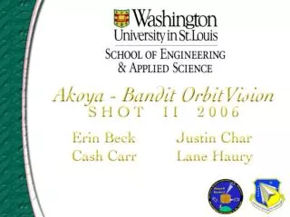
Akoya - BanditOrbitVision Washington University in St. Louis School of Engineering and Applied Science Erin Beck Justin Char Lane Haury Cash Carr
Goals: • Simulate the complete Akoya-Bandit camera-to-radio system • Photograph LED array as it would appear on Akoya in daylight • Photograph the Earth as it would appear to the Akoya Earthside camera
Akoya - Bandit: • Bandit is a 4 kg service vehicle housed within Akoya, a 25 kg parent satellite. On orbit, Bandit will undock from Akoya, navigate relative to it while completing simple to complex tasks, and redock. • Bandit navigates by observing a pattern of LEDs on Akoya’s surface and calculating position. • Two cameras aid navigation: • BanditCam: b/w camera that photographs LEDs, from which software determines position • AkoyaCam Dockside: color camera looking at Bandit from the dock, used for backup sighting of Bandit • One additional camera: • AkoyaCam Earthside: color camera to photograph Earth
SHOT II: • BanditCam: • Photographs sample LED array (b/w) • Transmits locally over 900 MHz radios, simulating the link between Bandit and Akoya. Then transmits over 2.4 GHz radios to ground, simulating the link from Akoya to ground. • AkoyaCam Earthside: • Photographs Earth horizon (color) • Transmits directly over 2.4 GHz radios to ground. • Accelerometer: • We hope to have an accelerometer as a secondary position sensor on Bandit. SHOT II includes one accelerometer; we are measuring its sensitivity.
Mass: 1.62 kg before tape Power: 20 1.5V Li batteries (72 W-hr for components, 18 W-hr for heaters) Radio frequencies: 900 MHz at 100 mW, 2.4 GHz at 1 W Balloon attachment: 1/4 inch threaded brass rod through center, attached with washer and nut on each end
Drop Test • Stair Pitch Test • Whip Test • Cooler Test • Table Test: • Photographs successfully downlinked across the table • At 115200 baud, we receive one 360x240 b/w image in ~30 sec or one 360x240 color image in ~80 sec.
Demonstrate end-to-end feasibility and functionality of Akoya-Bandit OrbitVision system. • Radios: Operate without interfering with each other • Lab test showed no interference. We could use the exact same system at higher power on orbit. • BanditCam: See LEDs. We may not be able to distinguish different shades as different colors, but we expect that the 100 millicandela Super Blue LEDs will be most visible. • AkoyaCam Earthside: We receive clear long-distance images, currently in one color only. • Accelerometer: The manufacturer claims extreme sensitivity, but it is unproven. We expect some readings, but have no prediction of magnitude.
Internal layout of components • Mobile Ground Station User Interface • End-to-end demonstration of BanditCam • Includes the following components and their connections: • BanditCam • 900 MHz transmitter and receiver • Frame Capture Board • Atmel (ATmega128) • 2.4 GHz transmitter and receiver • MGS computer