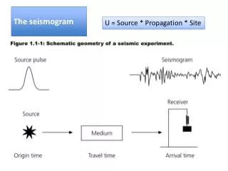
The seismogram
The seismogram. U = Source * Propagation * Site. POINT SOURCE APPROXIMATION. Distance r Wavelength l Fault dimension L. Far field terms dominates because r is relatively large. EXTENDED SOURCE FAULT PARAMETERS. surface. foot wall. Hanging wall. depth. length L. dip.

The seismogram
E N D
Presentation Transcript
The seismogram U = Source * Propagation * Site
POINT SOURCE APPROXIMATION Distance r Wavelength l Fault dimension L Far field terms dominates because r is relatively large
EXTENDED SOURCE FAULT PARAMETERS surface foot wall Hanging wall depth length L dip Fault dip width W fault N NUCLEATION POINT POSITION Fault azimuth Strike
EXTENDED SOURCE FAULT PARAMETERS
EXTENDED SOURCE PARAMETERIZATION An extended source is represented by the distribution of point sources at the each grid point surface
EXTENDED SOURCE FAULT PARAMETERS: Rupture Velocity surface fault Rupture velocity (vr)
EXTENDED SOURCE FAULT PARAMETERS: Slip surface y rake d fault t
COMPLEX SOURCE PHENOMENA Asperities and barriers asperities barriers
KINEMATICS EXTENDED SOURCE Slip on an earthquake fault Surface of the earth Depth Into the earth 100 km Distance along the fault plane
KINEMATICS EXTENDED SOURCE Slip on an earthquake fault: second 2.0
KINEMATICS EXTENDED SOURCE Slip on an earthquake fault: second 4.0
KINEMATICS EXTENDED SOURCE Slip on an earthquake fault: second 6.0
KINEMATICS EXTENDED SOURCE Slip on an earthquake fault: second 8.0
KINEMATICS EXTENDED SOURCE Slip on an earthquake fault: second 10.0
KINEMATICS EXTENDED SOURCE Slip on an earthquake fault: second 12.0
KINEMATICS EXTENDED SOURCE Slip on an earthquake fault: second 14.0
KINEMATICS EXTENDED SOURCE Slip on an earthquake fault: second 16.0
KINEMATICS EXTENDED SOURCE Slip on an earthquake fault: second 18.0
KINEMATICS EXTENDED SOURCE Slip on an earthquake fault: second 20.0
KINEMATICS EXTENDED SOURCE Slip on an earthquake fault: second 22.0
KINEMATICS EXTENDED SOURCE Slip on an earthquake fault: second 24.0
KINEMATICS EXTENDED SOURCE Final dislocation on the fault Rupture on a Fault Total slip during the 1992 Landers earthquake
. surface D(t) fault Rupture velocity (vr) Tr = rise time t tr t EXTENDED SOURCE FAULT PARAMETERS: Slip Velocity L • Rupture velocity is few km/s. By default, seismologist uses 3 km/s • The maximum duration d of the rupture is : • The slip amplitude on the fault scales with the length. • Slip velocity is around 1 m/s
Examples of multi-window STF’s: Examples of single-window STF’s: time CAVEAT: Using Appropriate Source Time Functions SOURCE TIME FUNCTIONS: The slip velocity history on each point on the fault is determined by the shape of the a priori assumed source time function.
Kinematic relations: Finite duration Fast initial acceleration Asymmetric shape Large peak value N.B. This parameterization allow us to constrain the time of positive slip acceleration, i.e. time of Vpeak
Focal Mechanism A. Kelly, USGS Focal Sphere around the source azimuth S. Stein and M. Wysession
x3 x3 x2 x2 x1 x1 Displacement Field from a double couple x1 x2
x3 x3 x2 x2 x1 x1 NODAL PLANE AND POLARITIES dilatation compression + - + -
The focal mechanism • Polarities of first arrivals - + + -
FOCAL MECHANISM DISPLACEMENT DISLOCATION compression Dilatation + - - +
Focal Mechanism & Radiation pattern b) Polarities of first P wave arrival • Stereographic projection
Focal Mechanims & Radiation patternCalculation • From polarities of first arrivals P-waves • From waveform modeling through moment tensor
Radiation patternFar Field Onde P Onde S
Radiation patternFar Field S P Nodal Planes
COMPLEX SOURCE PHENOMENA Directivity directive Non directive antidirective
COMPLEX SOURCE PHENOMENA Directivity effect on radiation Hirasawa (1965)
Fraunhofer Approximation The error in this approximation is