Download
1 / 49
490 likes | 506 Vues
Computer Communication & Networks. Lecture # 05 Physical Layer: Signals & Digital Transmission Nadeem Majeed Choudhary nadeem.majeed@uettaxila.edu.pk. Physical Layer Topics to Cover. Signals. Digital Transmission. Analog Transmission. Multiplexing. Transmission Media.

E N D
Computer Communication & Networks Lecture # 05 Physical Layer: Signals & Digital Transmission Nadeem Majeed Choudhary nadeem.majeed@uettaxila.edu.pk
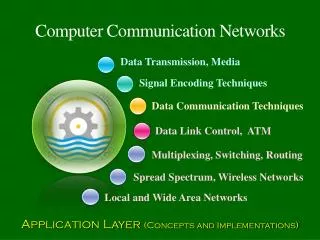
Physical Layer Topics to Cover Signals Digital Transmission Analog Transmission Multiplexing Transmission Media
Digital to Digital Conversion • The conversion involves three techniques:line coding,block coding, andscrambling. Line coding is always needed; block coding and scrambling may or may not be needed.
Line Coding • Converting a string of 1’s and 0’s (digital data) into a sequence of signals that denote the 1’s and 0’s. • For example a high voltage level (+V) could represent a “1” and a low voltage level (0 or -V) could represent a “0”.
Mapping Data symbols onto Signal levels • A data symbol (or element) can consist of a number of data bits: • 1 , 0 or • 11, 10, 01, …… • A data symbol can be coded into a single signal element or multiple signal elements • 1 -> +V, 0 -> -V • 1 -> +V and -V, 0 -> -V and +V • The ratio ‘r’ is the number of data elements carried by a signal element.
Relationship between data rate and signal rate • The data rate defines the number of bits sent per sec - bps. It is often referred to the bit rate. • The signal rate is the number of signal elements sent in a second and is measured in bauds. It is also referred to as the modulation rate. • Goal is to increase the data rate whilst reducing the baud rate.
Data rate and Baud rate • The baud or signal rate can be expressed as: S = c x N x 1/r bauds where N is data rate c is the case factor (worst, best & avg.) r is the ratio between data element & signal element
Pulse Rate Vs Bit Rate Example A signal has two data levels with a pulse duration of 1 ms. We calculate the pulse rate and bit rate as follows: Pulse Rate = 1/ 10-3= 1000 pulses/s Bit Rate = Pulse Rate x log2 L = 1000 x log2 2 = 1000 bps
Example 4.1 A signal is carrying data in which one data element is encoded as one signal element ( r = 1). If the bit rate is 100 kbps, what is the average value of the baud rate if c is between 0 and 1? Solution We assume that the average value of c is 1/2 . The baud rate is then
Note Although the actual bandwidth of a digital signal is infinite, the effective bandwidth is finite.
Example 4.2 The maximum data rate of a channel is Nmax = 2 × B × log2 L (defined by the Nyquist formula). Does this agree with the previous formula for Nmax? Solution A signal with L levels actually can carry log2L bits per level. If each level corresponds to one signal element and we assume the average case (c = 1/2), then we have
Example 3 In a digital transmission, the receiver clock is 0.1 percent faster than the sender clock. How many extra bits per second does the receiver receive if the data rate is 1 Kbps? How many if the data rate is 1 Mbps? Solution At 1 Kbps: 1000 bits sent 1001 bits received1 extra bps At 1 Mbps: 1,000,000 bits sent 1,001,000 bits received1000 extra bps
Considerations for choosing a good signal element referred to as line encoding • Baseline wandering - a receiver will evaluate the average power of the received signal (called the baseline) and use that to determine the value of the incoming data elements. If the incoming signal does not vary over a long period of time, the baseline will drift and thus cause errors in detection of incoming data elements. • A good line encoding scheme will prevent long runs of fixed amplitude.
Line encoding C/Cs • DC components - when the voltage level remains constant for long periods of time, there is an increase in the low frequencies of the signal. Most channels are bandpass and may not support the low frequencies. • This will require the removal of the dc component of a transmitted signal.
Line encoding C/Cs • Self synchronization - the clocks at the sender and the receiver must have the same bit interval. • If the receiver clock is faster or slower it will misinterpret the incoming bit stream.
Example 4.3 In a digital transmission, the receiver clock is 0.1 percent faster than the sender clock. How many extra bits per second does the receiver receive if the data rate is 1 kbps? How many if the data rate is 1 Mbps? Solution At 1 kbps, the receiver receives 1001 bps instead of 1000 bps. At 1 Mbps, the receiver receives 1,001,000 bps instead of 1,000,000 bps.
Line encoding C/Cs • Error detection - errors occur during transmission due to line impairments. • Some codes are constructed such that when an error occurs it can be detected. For example: a particular signal transition is not part of the code. When it occurs, the receiver will know that a symbol error has occurred.
Line encoding C/Cs • Noise and interference - there are line encoding techniques that make the transmitted signal “immune” to noise and interference. • This means that the signal cannot be corrupted, it is stronger than error detection.
Line encoding C/Cs • Complexity - the more robust and resilient the code, the more complex it is to implement and the price is often paid in baud rate or required bandwidth.
Note In unipolar encoding, we use only one voltage level.
Note In polar encoding, we use two voltage levels: positive & negative
Note In NRZ-L the level of the voltage determines the value of the bit. In NRZ-I the inversion or the lack of inversion determines the value of the bit.
Note In Manchester and differential Manchester encoding, the transition at the middle of the bit is used for synchronization.
Note In bipolar encoding, we use three levels: positive, zero, and negative.
Transmission Modes • The transmission of binary data across a link can be accomplished in either parallel or serial mode. In parallel mode, multiple bits are sent with each clock tick. In serial mode, 1 bit is sent with each clock tick. While there is only one way to send parallel data, there are two subclasses of serial transmission: asynchronous, synchronous.
Note In asynchronous transmission, we send 1 start bit (0) at the beginning and 1 or more stop bits (1s) at the end of each byte. There may be a gap between each byte.
Note Asynchronous here means “asynchronous at the byte level,” but the bits are still synchronized; their durations are the same.
Note In synchronous transmission, we send bits one after another without start or stop bits or gaps. It is the responsibility of the receiver to group the bits.
Readings • Chapter 4 (B.A Forouzan) • Section 4.1, 4.2, 4.3