Download
1 / 47
650 likes | 1.06k Vues
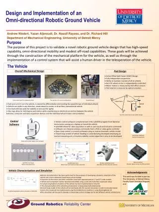
Design and Vehicle Implementation of an Adaptive ABS. J. Tigelaar 13 May 2011. 1. Design and Vehicle Implementation of an Adaptive ABS. Design and Vehicle Implementation of an Adaptive ABS. Goal. … Taking the research one step further ….

E N D
Design and Vehicle Implementation of an Adaptive ABS J. Tigelaar 13 May 2011 1 Design and VehicleImplementation of anAdaptive ABS
Goal …Taking the research one step further… • Research on ABS is part of a larger research objective • Load based vehicle dynamics control • Decrease in system complexity • Decrease in development cost • Increase in performance Novel ABS algorithm evaluated on testbench. Limitations: no changing load on tyre no changing friction coefficient Goal:Evaluate ABS robustness (Fz, µ) and implement in test vehicle Design and VehicleImplementation of anAdaptive ABS
Contents The next ~25 min • Why do we need ABS? • How does it work? • PART 1 -> Algorithm Design: increase its robustness • Simulation evaluation • PART 2 -> Vehicle Implementation: implement in test vehicle • Track testing • Does Load Based Sensing offer improvements in performance? Design and VehicleImplementation of anAdaptive ABS
Why does one need ABS? ABS video This video containsshocking images and is thereforenotsuitablefor BMW fans. Introduction to ABS
Why does one need ABS? ABS video This video containsshocking images and is thereforenotsuitablefor BMW fans. To prevent wheel-lock What happens at wheel-lock? Introduction to ABS
Braking Forces are generated at tyre-road contact patch • Many different models of tyre-road interaction [Jazar, Reza N. (2008): Vehicledynamics. Theory and application. New York, NY: Springer.] Introduction to ABS
Braking (Fx) LongitudinalTyreForces Fx/Fz maxFx -> BD Slip λ Introduction to ABS
Braking (Fy) LateralTyreForces FY/FZ Steerability -> front Stability -> rear Slip λ [Tanelli, M.; Corno, M.; Boniolo, I.; Savaresi, S.M. (2009): Active braking control of two-wheeled vehicles on curves.] Introduction to ABS
Re-cap Prevent wheel-lock in order to: • Maintain steerability • Maintain stability • Decrease braking distance Trade-offbetweenFx and Fy Idealoperating range Normalizedforce Many different controlstrategies to achievethis Slip λ Introduction to ABS
Control How does ABS work? How does ABS cycle? Hold/Decrease/Increase pressure Valves Wheel speed sensor 5 Phase : hybridwheeldecelerationbasedlogic Introduction to ABS
A 2-Phase example A hybridwheeldecelerationbasedlogic Continuous and discrete states Normalizedforce Slip λ Algorithm Design
ABS 5-Phase algorithm (x1 and x2) A hybridwheeldecelerationbasedlogic X1 : Wheel slip offset X2 : Wheel acceleration offset Set of dynamicequations Algorithm Design
5-Phase algorithm A hybridwheeldecelerationbasedlogic Stating that • Brake torque will either be kept constant or change rapidly • Switching between torques is triggered by thresholds • Thresholds are wheel deceleration based Regulation logic chosen as such to keep unmeasured x1 small close to 0 Algorithm Design
5-Phase Automaton The hybridautomaton State transistionsgovernedbyguardconditions. Evolution of continuousstates is determinedbydynamic system. [Pasillas-Lépine, W. (2006): Hybrid modeling and limit cycle analysis for a class of five-phase anti-lock brake algorithms.] Algorithm Design
5-Phase 1st Integrals Phase-plane (x1-x2) trajectories For constant brake torque For large torque variations, Approximate first integral is Approximation error with Algorithm Design
5-Phase Criteria The criteria Satisfying all 5 criteria Criterion 1 : Criterion 2 : Criterion 3 : Stabilityguaranteed Criterion 4 : Criterion 5 : Algorithm Design
Load transfer Static and Dynamic dynamic static [Jazar, Reza N. (2008): Vehicledynamics. Theory and application. New York, NY: Springer.] Algorithm Design
Fz and Stability dynamic The fifth criteria static • [B] Maintain stability at lower loads -> retune (ε5) thresholds (limited) • [C] Maintain stability at lower µ’s -> T rate increase in phase 5 Load transfer [N] Frictioncoefficient µ Algorithm Design
5-Phase Simulation Simulationresults • 4 wheel car model. Algorithm runs separately on each wheel. • Straight line braking starting from 150 km/h • Cost functions are defined as: • Maximum slip • Braking distance Fy Fx Algorithm Design
5-Phase Simulation at high µ Simulationresults (FL wheel) • Observed that as µ increases, the algorithm cycles within stable zone. LongitudinalTyreForce [N] Larger force drop occurs during cycling Slip λ Algorithm Design
5-Phase Simulation Limit Cycle Simulationresults Wheel acceleration offset [m/s2] • 5th threshold determines the slip level reached in the unstable zone Wheel slip offset x1 [%] Algorithm Design
5-Phase Simulation at low µ Simulationresults • An increased ε5 would be beneficial for higher µ, but adverse for low µ LongitudinalTyreForce [N] ε5 = 30 ε5 = 50 ε5 = 30 ε5 = 50 A dynamicthreshold Slip λ Algorithm Design
5-Phase Dynamic Threshold Dynamicfifththreshold • Fifth threshold can be freely defined • Friction coefficient cannot be measured directly ε5 FX/FZ Algorithm Design
Adaptive 5-Phase Results Results - improvements • 20 % decrease in braking distance • Maximum slip level is maintained Braking distance [m] Frictioncoefficient front ε5=30 ε5=50 rear Frictioncoefficient Frictioncoefficient Theoretical ε5=d ε5 Algorithm Design
Adaptive 5-Phase Video Results - improvements • VIDEOS – steering manoeuvre (2m to the left) • White car : No ABS • Red car : ABS with standard 5-Phase • Blue car : ABS with adaptive 5-Phase Lanechangeduring braking from 150km/h Algorithm Design
Vehicle modifications (VM) BMW 530 (E60) VehicleImplementation
VM Principle Basicprinciple • Original ABS serves as a benchmark, driver can switch • ECU (sensor input and required control decisions) • Power stage (amplify the control signal) • Hydraulic unit (actuate the solenoid valves) ABS module Individualwheelcontrol Dummy ABS module How? VehicleImplementation
VM dSpace Basicprinciple dSpaceAutobox enables receiving and sending signals IN: wheel speed (tapped) brake pressure (installed) OUT: control action valves control action pump VehicleImplementation
VM Brake circuit Brakepressure sensors 3 2 1 6 5 7 8 4 [Robert Bosch GmbH (2007): Automotive Electrics Automotive Electronics. 5th: Wiley.] VehicleImplementation
VM T-split Brakepressure sensors VehicleImplementation
VM dSpace Basicprinciple dSpaceAutobox enables receiving and sending signals IN: wheel speed (tapped) brake pressure (installed) OUT: control action for valves (hold and decrease presssure) control action for pump (increase pressure) VehicleImplementation
VM ECU The ABS Module The ECU Still being reverse engineered. VehicleImplementation
VM Conventional System overview - conventional VehicleImplementation
VM Novel System overview - novel VehicleImplementation
VM Track testing VehicleImplementation
Conclusions Anoverview PART 1 • Through the use of load sensing: Dynamic thresholds can significantly improve ABS performance Decreased braking distance by 20% Maintained lateral stability and steerability PART 2 • Vehicle modification allow performance evaluation Conclusion
? Conclusion
Braking The braking process
Further research TU Delft • ABS Activation Logic • Different than slip based (e.g. brake pedal) • Coupling of all 4 wheels • Synchronization on front • A-Synchronization on rear • Modeling of brake efficiency • Thermal effects Extra Slides
Future of ABS Possibleoutcomes • From motion based to force based control systems • Electro-MechanicalBrakes • Forcemodulation is continous (not discrete) • No vibrations to brakepedal (safety) • No toxicbrakefluid (leakage) • From threshold based control rules (wheel deceleration) move to slip control (multi-applications, ABS, ESP, TCS, …) • ABS simplification Extra Slides
Controller Area Network (CAN) Tests show a deviation in time interval reception, thus large jumps in value Average time interval over all 4 wheel signals = 60 msec Wheel speed [km/h] Occurrence Time [s] Time steps
Wheel speed Active Inductance Sensors • Sensechange in magnetic field due to incremental ring • Contains 3 Hall sensors • 1 and 3 serve forvelocityestimation • 2 serves fordirection of rotation • Derivewheeldeceleration is challenging. Twomainmethods • Lines-Per-Period • Fixed-position Extra Slides
Bosch ABS Based on: Heuristics Requires extensive tuning per vehicle model Rule-of-Thumb System is unclear -> contains many control rules System complexity ever increasing Also uses (amongst others) wheel deceleration values
VM PWM Basicprinciple • Pulse-Width Modulated signal for valve hold control and pump increase control • Additional I/O signal for valve release control 50% dutycycle