Mobility Architecture: Overview and Approaches for 802.21 Discussion
This presentation by Alan Carlton from Interdigital Communications explores the Mobile System Terminology, Cellular Mobility Models, WLAN Mobility Models, and General Scope of the 802.21 standard. It covers various modes, operations, and decision-making processes in mobile systems.

Mobility Architecture: Overview and Approaches for 802.21 Discussion
E N D
Presentation Transcript
Defining Layer 2.5 Alan Carlton Interdigital Communications alan.carlton@interdigital.com Alan Carlton, Interdigital Communications
Objectives • To stimulate a discussion on the preferred 802.21 Mobility Architecture • To stimulate a discussion on the scope of 802.21 • To review Typical Mobile System architecture approaches as they may pertain to the broad objectives of 802.21 Alan Carlton, Interdigital Communications
Mobile System Terminology Used in this Presentation • Two key modes exist for typical mobile systems - IDLE mode and CONNECTED mode: • IDLE mode (STA) characteristics • No User service, monitoring of paging channels, available service request channels • 100% of Receiver available for Downlink Measurements • Background coordination, unscheduled AP/technology reselection • CONNECTED mode (STA) characteristics • Active User service (e.g. a call), Handover possible • Limited Receiver availability for measurements (User service takes priority) • Fully Coordinated, scheduled AP/technology handover • Selection: • Prior to entering IDLE mode (e.g. at Power up) the STA must perform selection in order to determine the best AP and technology available for service • Reselection: • While in IDLE mode (i.e. No User service) the STA must continuously examine neighbor AP (and different technology AP). Upon determination of a ‘better’ AP the STA will transition over to the new AP • Handover • While in CONNECTED mode (i.e. Active User Service) a handover occurs upon transition from one AP to another AP (possibly using a different technology) offering significantly better service. In the ideal case this transition will occur without noticeable interruption of the Active User Service. Alan Carlton, Interdigital Communications
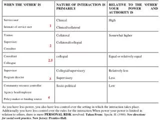
GSM/900 AP GSM1800 GSM900 GSM900 AP AP AP AP EDGE The Cellular Mobility Model e.g. Switch, Server Network Handover Policy Function e.g. 2G BSC, 3G RNC Full Mobility Support Radio Network Semi-Static Frequency Assignments AP GSM900 AP FDD e.g. GSM Base Station e.g. FDD Node B Cellular STA e.g. 2G MS, 3G UE Centralized Radio Resource Management Approach Alan Carlton, Interdigital Communications
The Cellular Mobility Model (Continued) • Radio Network Characterization: • Centralized RRM approach (Semi-Static Frequency assignments in each AP) • Some Radio Planning Required • IDLE Mode Operation: • Intra-technology (e.g. GSM to GSM) • AP Selection/Reselection decision made in STA supported by System information broadcast by the Handover Policy function (Policy defined in the Handover Policy function) • Inter-technology (e.g. GSM to FDD/WCDMA) • AP Selection/Reselection decision made in STA supported by System information broadcast at the Handover Policy function (Policy defined in the Handover Policy function) • CONNECTED Mode Operation: • Intra-technology • AP handover decision made in the Handover Controller function supported by measurements made by the STA and sent to the Handover Policy function via L3 signaling (Policy defined in the Handover Policy function) • Inter-technology • AP handover decision made in the Handover Policy function supported by measurements made by the STA and sent to the Handover Policy function via L3 signaling (Policy defined in the Handover Policy function) Alan Carlton, Interdigital Communications
802.11b 802.11a AP AP 802.11 AP AP AP 802.16 802.11n The WLAN Mobility Model - Current e.g. Gateway, Router Network Limited Mobility Support Radio Network Dynamic Frequency Assignments 802.11a 802.11 AP AP IEEE 802.X STA Distributed Radio Resource Management Approach Alan Carlton, Interdigital Communications
The WLAN Mobility Model (Continued) • Radio Network Characterization: • Distributed RRM approach (Dynamic Frequency assignments in each AP) • Radio Planning Not Required • IDLE Mode Operation: • Intra-technology (e.g. 802.11a to 802.11a) • AP Selection/Reselection decision made autonomously in STA (Policy defined in the STA) • Inter-technology (e.g. 802.11 to 802.16) • SELECTION/RESELECTION NOT STANDARDIZED – SCOPE OF 802.21 • CONNECTED Mode Operation: • Intra-technology • HANDOVER NOT STANDARDIZED – SCOPE OF 802.21 • Inter-technology • HANDOVER NOT STANDARDIZED – SCOPE OF 802.21 General Scope of 802.21 Alan Carlton, Interdigital Communications
Network The WLAN Mobility Model – Enhanced (802.21) e.g. Gateway, Router DISTRIBUTED Handover Policy Function CENTRALIZED Handover Policy Function STA ONLY SYSTEM Option A Option B Enhanced Mobility Support (802.21) Radio Network Dynamic Frequency Assignments 802.11b 802.11a 802.11 802.11a AP AP AP 802.11 AP AP AP AP 802.16 802.11n IEEE 802.X STA Two Basic Options Are Considered Alan Carlton, Interdigital Communications
Option A & Option B Definition • IDLE Mode Operation: • Intra-technology (e.g. 802.11a to 802.11a) • AP Selection/Reselection decision made autonomously in STA (Policy defined in the STA) • Inter-technology (e.g. 802.11 to 802.16) [SCOPE OF 802.21] • Option A: AP Selection/Reselection decision made autonomously in STA (Policy defined in the STA) • Option B: AP Selection/Reselection decision made in STA supported by System information broadcast at the Handover Policyfunction level (Policy defined in the Handover Policy Function) • CONNECTED Mode Operation: • Intra-technology [SCOPE OF 802.21] • Option A: AP handover decision made autonomously in STA (Policy defined in the STA) • Option B:AP handover decision made in the Handover Policyfunction supported by measurements made by the STA and sent to the Handover Policyfunction via new signaling mechanisms (Policy defined in the Handover Policy Function) • Inter-technology [SCOPE OF 802.21] • Option A: AP handover decision made autonomously in the STA (Policy defined in the STA) • Option B:AP handover decision made in the Handover Policyfunction supported by measurements made by the STA and sent to the Handover Policyfunction via new signaling mechanisms (Policy defined in the Handover Policy Function) Alan Carlton, Interdigital Communications
Option A: DISTRIBUTED Handover Policy Function • Intra/Inter Technology Reselection decision made autonomously by the STA • Adequate but sub-optimal solution • Intra/Inter Technology Handover decision made autonomously by the STA • Slow Handover Solution /Really just an extension of Reselection and would be characterized as such in a typical Mobile system • Break and then Make strategy (Resource availability not guaranteed) • Adequate solution for non real-time services • Unacceptable solution for real time services (such as voice) • Poorly scaleable solution Local MIB 802.11 Model MAC Sublayer ME MAC Sublayer Handover Policy Function PLCP Sublayer Physical Sublayer ME PMD Sublayer STA Functional Architecture Concept Option A Provides a Very Limited Mobility Solution Alan Carlton, Interdigital Communications
Option B: CENTRALIZED Handover Policy Function Handover • Intra/Inter Technology Reselection decision supported by System Information • Optimal solution • Intra/Inter Technology Handover decision coordinated by RPF and supported by measurement reports and System signaling • Fast Handover Solution • Make and then Break strategy (Resource availability is guaranteed) • Adequate solution for non real-time services • Acceptable solution for real time services (such as voice) • Easily scaleable solution System Info Measurements 802.11 Model System HPF MAC Sublayer ME MAC Sublayer Layer 2.5 Signaling/Control Function PLCP Sublayer Physical Sublayer ME PMD Sublayer STA Functional Architecture Concept Option B Provides a Full Mobility Solution – Typical Mobile System Architecture Approach Alan Carlton, Interdigital Communications
IEEE 802.xx STA IP e.g. Mobile IP Convergence Layer 2.5 IEEE 802.21 IEEE 802.2 LLC Transparent Mode Option MAC Physical GSM RR 3G RRC IEEE 802.3,11,16… Typical Mobile System Architecture compared to 802.X GPRS (2G) STA 3GPP (3G) STA IP IP Mobility Protocol (MM) Mobility Protocol (MM) Convergence Convergence Network GSM 04.18 3GPP 25.331 RLC RLC Transparent Mode Option Transparent Mode Option Data Link MAC MAC Physical Physical Physical User Plane User Plane Control Plane Control Plane In a Full Mobility Solution Layer 2.5 is a key enabler Alan Carlton, Interdigital Communications
Both Functions are required in order to support a Full Mobility Solution Key Protocol Functions Mobility Protocol Resource Control Protocol (e.g. GSM-MM/MAP, Mobile IP…) (e.g. GSM-RR, 3GPP RRC, L2.5?) • Discovery • Registration • Tunneling • Termination (or Paging) • Handover at Network Level • Security • System Information • Termination (or Paging) • Cell Selection/Reselection • Establishment • Release • Measurement Reporting • Power Control • Handover at Radio Level Alan Carlton, Interdigital Communications
Network Example: End to End Functional Configuration CENTRALIZED Handover Policy Function 802.11 802.11a AP IEEE 802.X STA 802.11a AP e.g. Gateway, Router AP Station Function Network/Radio Network Functions Higher Layers Higher Layers Mobility Protocol Mobility Protocol U-Plane U-Plane Layer 2.5 Layer 2.5 Handover Policy Function LLC Link Layer MAC MAC Lower Layers Lower Layers Physical Physical The RHF may be defined as logical functional entity Alan Carlton, Interdigital Communications
Conclusions • The Option B architecture with a centralized Handover Policy Function would seem to be the most promising approach and is recommended. • In order to provide a full mobility solution both Radio Mobility (e.g. GSM RR) and Network Mobility (e.g. Mobile IP) protocol functionality is required in the system. • Layer 2.5 is a key enabler in a full mobility solution. • In order to support the Option B Architecture 802.21 should define a Layer 2.5 Signaling and Control Protocol with some similar properties to RR style protocols currently used in typical Mobile systems. • The Handover Policy Function may be defined as a logical entity. It is not necessary to define any restrictions in the Standard on its location in a physical implementation though some recommendations may be made if valuable. • The Option B architecture closely maps to well proved typical Mobility System architectures and will simplify future advanced interworking scenarios unanticipated at this time (e.g. tightly coupled handover). • The Centralized Handover Policy Functional architecture may be easily extended to support Wireless to Wired interworking scenarios e.g. the Handover policy upon connecting a Wireless device to a Wireline system may be automatic handover. Alan Carlton, Interdigital Communications