
BDSA – Deployment and Documentation
BDSA – Deployment and Documentation. Jakob E. Bardram. Today. UML Deployment & Component Diagrams [OOAD] ch. 38 Architecture Documentation [OOAD] ch. 39 UML N+1 (4+1) View Model The Project!. UML Deployment and Component Diagrams. UML Deployment Diagram. UML Deployment Diagram

BDSA – Deployment and Documentation
E N D
Presentation Transcript
BDSA – Deployment and Documentation Jakob E. Bardram
Today • UML Deployment & Component Diagrams • [OOAD] ch. 38 • Architecture Documentation • [OOAD] ch. 39 • UML • N+1 (4+1) View Model • The Project!
UML Deployment Diagram • UML Deployment Diagram • shows the assignment of software • to computational nodes • i.e. the deployment of software elements • to the physical architecture • Physical Node • device – i.e. physical computing resource • PC, PDA, phone, server, ... • execution environment node (EEN) – a software computing resource • OS, VM, DB, Web browser, EJB container, ...
UML Component Diagram • Component • A component represents a modular part of a system that encapsulates its contents an whose manifestation is replaceable within its environment. • A component defines its behavior in terms of provided and required interfaces. • UML Components are design level perspectives • they do not exist in the concrete software perspective • but may map to a set of files (in e.g. a package)
Software Architecture Document • The SAD • the overall picture & idea of the system architecture • architectural decisions (using technical memos) • N+1 architectural views • Architectural View • a view of the system architecture from a given perspective • focus on • structure, modularity, essential components, main control flow • a window on the system from a particular perspective – emphasize something, ignores the rest
Logical View – static • Class & Package diagrams
Logical View – dynamic Sequence Diagrams
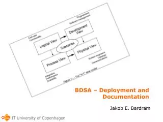
The 4+1 View Model • Kruchten, P. The 4+1 View Model of Architecture. IEEE Software 12(6), 1995. • 4 Views • Logical – conceptual organization • Process – execution and threads • Physical – software deployment on physical nodes • Data – data flow, persistence schema, O-R mapping • +1 View • Use cases – summary of most important use cases • + non-functional requirements • NB! Remember the motivation = the text! • explain WHY the architecture is the way it is...
Software Architecture Document • Architectural Representation • Architectural Factors • Architectural Decisions • 4 Views • Logical View • Deployment View • Process View • Data View • +1 View • Use-Case View • Other Views • Security, Implementation, Development, ...