Industrial Programmable Logic Controllers (PLCs)
Industrial Programmable Logic Controllers (PLCs). Eng. R. L. Nkumbwa Copperbelt University School of Technology 2010. Programmable Logic Controllers (PLC’s). A programmable logic controller (PLC) is a special purpose computer aimed at implementing control solutions.

Industrial Programmable Logic Controllers (PLCs)
E N D
Presentation Transcript
Industrial Programmable Logic Controllers (PLCs) Eng. R. L. Nkumbwa Copperbelt University School of Technology 2010
Programmable Logic Controllers (PLC’s) • A programmable logic controller (PLC) is a special purpose computer aimed at implementing control solutions. • Historically PLC’s have been used mainly for on-off or logic type applications. • However, modern PLC’s have become increasingly sophisticated and can now cover quite complex control tasks. Eng. R. L. Nkumbwa @ CBU 2010
Programmable Logic Controllers • These notes emphasize the switching capability of a PLC. However, the reader is urged to think of the dynamics of the underlying system. • For example, we recently heard of a seemingly straightforward application of a PLC to a reservoir level control problem. • The algorithm had many features but in essence conformed to the rule that if the level was too low then the pumping rate should be increased. Eng. R. L. Nkumbwa @ CBU 2010
Programmable Logic Controllers • This can be seen as an approximate form of integral control. • However, pure integral control when applied to a tank (which is also an integrator) will lead to self sustained oscillations. • The reader is encouraged to verify this by drawing a root locus plot for the closed loop poles. • The moral of this story is that when implementing a controller in a PLC one needs to consider the combined dynamics of the control law and system. • In this way a PLC is no different from any other form of control implementation platform. Eng. R. L. Nkumbwa @ CBU 2010
Industrial Robustness of PLC’s • If you have ever had a personal computer lock-up or reset in the middle of something important you will appreciate that a similar failure in a large industrial application would have severe consequences. • A PLC is simply an industrial computer designed to be durable enough to withstand the rigors of industrial applications. Eng. R. L. Nkumbwa @ CBU 2010
Industrial Robustness of PLC’s • It is common in the mining industry to have PLC’s on large mobile equipment to monitor and control everything from lights to large electrical drives. • The vibration and operating temperature of this environment require the use of specialized control equipment such as PLC’s. Eng. R. L. Nkumbwa @ CBU 2010
Some Physical Tolerances of leading PLC brands Eng. R. L. Nkumbwa @ CBU 2010
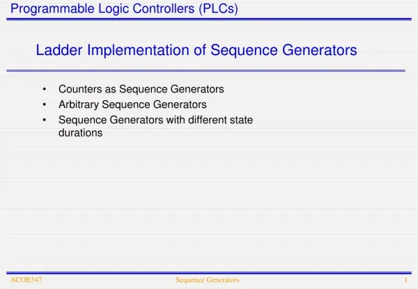
Typical Areas of Application • For past 30 years PLC’s have been in the first level of control because of their ability to run uninterrupted for extended periods of time (usually measured in months or even years). • The PLC layer in industrial applications is shown in figure below Eng. R. L. Nkumbwa @ CBU 2010
Control hierarchy of PLC’s Eng. R. L. Nkumbwa @ CBU 2010
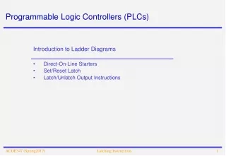
Ladder Logic • The remained of this chapter will look at Ladder Logic, which is the most common programming structure used in PLC’s. • Several examples of common Ladder Logic programs will be demonstrated to show the simple structure of this coding style. Eng. R. L. Nkumbwa @ CBU 2010
Relay Ladder Logic • Ladder logic is possibly the simplest programming language. • The principle behind the language is illustrated by a simple electrical relay. (Electrical relay logic preceded PLC’s as initially all logic was implemented in hard wired panels using actual relays, timer, Counters etc.) Eng. R. L. Nkumbwa @ CBU 2010
Simple Relay Circuit Eng. R. L. Nkumbwa @ CBU 2010
Circuit representation in Ladder Logic • The above circuit is represented in Ladder logic as shown in figure below (only the low voltage circuit is used in ladder logic diagrams): Eng. R. L. Nkumbwa @ CBU 2010
Boolean Logic • The above diagram can be expressed in Boolean logic “Motor Coil = Switch”, ie if the Switch is on the Motor coil is energized and Motor is activated. • All ladder logic takes the form of that shown in Figure above. • Thus it connects the positive and neutral rail representing positive and negative power supply to the relay. Eng. R. L. Nkumbwa @ CBU 2010
Ladder Logic Instructions • The three most common instructions in ladder logic are: Eng. R. L. Nkumbwa @ CBU 2010
PLC Switching • The majority of simple PLC switching tasks can be implemented using these simple instructions. • However there exists a set of 60 to 100 individual instructions such as those above which form the complete PLC language. • Other functions vary from simple timers and counters to more sophisticated control functions such as PID controllers and advanced arithmetic functions. Eng. R. L. Nkumbwa @ CBU 2010
Multi Input/Output Rungs Eng. R. L. Nkumbwa @ CBU 2010
Multi Input/Output Rungs • Each of the inputs in series such as ‘S2’ and ‘S3’ are equivalent to the Boolean “AND”{.} statement while a “Bridge” in a rung is seen as an “OR”{+} statement. • In the case shown in Figure above the Boolean expression for the Coil is: Eng. R. L. Nkumbwa @ CBU 2010
Multi Output Rungs • It is also possible to have multi output rungs provided the OTE instructions are never placed is series, they must always be in parallel and in contact with the Neutral (right) rail, as shown in figure below. (While multi output rungs are necessary in some cases, it is often beneficial to divide the rung into several smaller rungs for the purpose of program clarity) Eng. R. L. Nkumbwa @ CBU 2010
Multi Output Rungs Eng. R. L. Nkumbwa @ CBU 2010
Start-Stop Rung • Any large rung can always be broken down into simple Boolean expressions such as for the simple rungs shown above. • Just as common electrical relays have auxiliary outputs, which are used for feedback and indication, a similar strategy is used in ladder logic. • To demonstrate this point a simple START/STOP rung is examined. • Two Push Buttons (PB) are used for the ‘start’ and ‘stop’ inputs (Push buttons return a High or Low signal to the PLC only for the duration during which the button is held down), Consider the logic shown in Figure below. Eng. R. L. Nkumbwa @ CBU 2010
Use of Auxiliary Output Eng. R. L. Nkumbwa @ CBU 2010
Push Button Example • In this case the push buttons are “normally open” i.e. they return a low signal in their normal position and a high signal when pressed. • Initially assume the Coil output is off, and the Push Buttons (PB) not activated so they are also off. • When the ‘Start PB’ is pressed the top path through the rung is satisfied with start = 1and stop = 0 so the coil is turned ON. • Note this also satisfies the bottom path through the rung on the next scan since coil = 1 and stop = 0. • When the start button is released the top path through the rung becomes false but the rung is still satisfied by the bottom path, ie the coil remains on after the start PB is released. Eng. R. L. Nkumbwa @ CBU 2010
Push Button Example • Pressing the ‘stop’ button (stop =1) breaks the rung so the coil is turned OFF and remains off after the stop button is released. Eng. R. L. Nkumbwa @ CBU 2010
Other PLC Programming languages • While Ladder logic is the most common form of PLC language it is worth noting that other languages do exist which where developed in conjunction with Relay Ladder Logic. Eng. R. L. Nkumbwa @ CBU 2010
Other Languages • Blocks are built from small ladder logic subroutines and used through the code as user defined ladder logic instructions, the advantages of this approach is the reduction of repetitive ladder logic code. • Sequential Function Chart (SFC) programming is similar to programming by computer flow chart. In SFC the program advances step by step through various blocks (where action happens such as a motor is started). • Transition conditions determine when the program advances from one block to another. • Both the action blocks and the transition conditions are created using ladder diagrams. • Structured text, uses simple instructions common to medium level programming languages: If , While, Then etc. Eng. R. L. Nkumbwa @ CBU 2010
Other Languages • Note: Some programming packages allow the user to switch between Relay Ladder Logic and Structured text representations of the code. Eng. R. L. Nkumbwa @ CBU 2010
PLC Modules • The modular nature of PLC components makes the design, instillation and maintenance of the first level of control much simpler. • Similar to the peripheral devices, which can be obtained for a personal computer, there are literally thousands of interface modules supported by PLC’s. • While these modules may be numerous they all have the same function, obtaining or delivering control signals and information between the measurement level and the operator interface level. • The modular nature is possibly the greatest strength of PLC’s and several common modules will be described below. Eng. R. L. Nkumbwa @ CBU 2010
Digital Inputs/Outputs (I/O) • By far the most common industrial signals used in PLC’s are simple digital control signals. • Referred to as Digital I/O (Digital input/output), they can be measured in there thousands for substantial industrial plants. • They are used to measure an amazing verity of events. • The most common digital signal encountered is a simple switch, A switch is nothing more than an electrical switch used to indicate some physical position. Eng. R. L. Nkumbwa @ CBU 2010
Digital Inputs/Outputs (I/O) • Digital I/O signals come in many forms from 12 Volt DC to 240 Volt AC, but the most common industrial signals are 24Volt DC and 120V AC. • There are Digital I/O modules to measure all of these signals, an extra variation is the number of signals per module ranging from 8, 16 and 32 etc. • Most digital modules have electrical protection usually in the form of optocoupling to prevent damage to the PLC from standard electrical faults. Eng. R. L. Nkumbwa @ CBU 2010
Analogue Inputs/Outputs (I/O) • Analogue signals enter and leave the PLC in voltage and current form, The resolution of most analogue signals is between 11 and 16 bits. • While voltage is commonly used in practice it can be sensitive to noise (induced voltages in electrical equipment rooms can be substantial) This makes current control the superior choice. • The most common analogue signals appear in the form of a 4-20mA current signal, i.e. Eng. R. L. Nkumbwa @ CBU 2010
Analogue Inputs/Outputs (I/O) • A signal of 4.0mA equates to zero, • A signal of 20mA equates to 2048 for an 11 bit input, • The reason for the 4.0mA starting point is a fail-safe feature, if the instrument fails or the signal cable is damaged the current falls to zero and the PLC can alarm the operating system of the failure immediately. • This fail-safe feature is not possible for voltage signals which pass through zero volts. Eng. R. L. Nkumbwa @ CBU 2010
Other interface modules • Digital I/O and Analogue I/O signals comprise the vast majority of PLC signals. • However, not all devices can be controlled by these simple signals and it is often required that PLC’s communicate to foreign instruments using many different communications protocols, • Again in most instances there is simply a module predesigned to make this interface possible. • Some examples include RS232, RS485, DH485, DH+, Modbus, Ethernet etc. Eng. R. L. Nkumbwa @ CBU 2010
Memory (Addressing , Internal Registers) • The memory in PLC’s needs to be predefined by the programmer, similar to defining variables in standard programming. • The memory is divided into data files, each data file has a unique number and a character prefix which refers to the type of data. • For example, in the Allen Bradley PLC-5 system, we have; Eng. R. L. Nkumbwa @ CBU 2010
Allen Bradley PLC-5 System Eng. R. L. Nkumbwa @ CBU 2010
Allen Bradley PLC-5 System • The ASCII character (or characters) denotes the data area type. Other types of defined words include T-timers, C-counters and S-status registers etc. • Note that the Output and Input numbers are dropped from file 0 and 1 respectively, this is because these files are not programmable. • Status file 2 (S2:##) is also fixed within Allen Bradley PLC’s. (Status bits include such information as arithmetic overflow warnings, communication status and processor time and dates etc) Eng. R. L. Nkumbwa @ CBU 2010
Allen Bradley PLC-5 System • The internal data areas of Integers and Floating point addresses simply point to a linear memory region. • However the Input and Output address actually correspond to a physical address. For example I:12/03 has the format, I:{Rack address}{slot number}/{Input number}. • Physically this is the 3rd input on the 2nd slot in the 1st Rack. • This input is show below in figure, Eng. R. L. Nkumbwa @ CBU 2010
Physical I/O Addressing Eng. R. L. Nkumbwa @ CBU 2010
Physical I/O Addressing • Note: PLC’s usually start counting from zero and use the octal counting system. ie an eight slot rack will have slots numbered from 0 to 7. • This is the case for racks, slots and input numbers. • So the first possible input would be Rack 0, slot 1 input 0 (Slot 0 in Rack 0 is not available for inputs since it is always reserved for the Central Processing Unit, CPU) Eng. R. L. Nkumbwa @ CBU 2010
Addressing Format • The addressing format has been demonstrated here because in writing a PLC program the address is used by the PLC in the ladder logic. • For example, if in the Start /Stop logic of figure (6) the Start PB = I:13/04 and Stop PB = I:13/05 and the output Coil = O:12/03 then the ladder logic would look more like figure below Eng. R. L. Nkumbwa @ CBU 2010
Start/Stop Addressing Example Eng. R. L. Nkumbwa @ CBU 2010
PLC Programming Architecture • A PLC program can be divided into many small subroutines. In this respect PLC’s replace function and procedures with subroutines. • Each subroutine is executed from top to bottom in a predetermined order. • Once all the subroutines have been scanned it simply begins again with the first subroutine. • The nature of subroutines makes a modular programming structure possible, It is always beneficial to group segments of code which serve similar purposes. Eng. R. L. Nkumbwa @ CBU 2010
PLC Programming Architecture • For example a program may be divided in the following way: • Subroutine U:20 – Pumps sequencing logic file. • Subroutine U:21 – Pump No.1 alarming and drive file. • Subroutine U:22 – Pump No.2 alarming and drive file. • Subroutine U;23 – Pump No.3 alarming and drive file. Eng. R. L. Nkumbwa @ CBU 2010
PLC Programming Architecture • Here subroutine 20 controls the sequencing of 21,22 and 23 while the drive files are virtually identical for each pump by starting and stopping the pump while reporting alarms and the healthy status to file 20. • Fault finding problems in the code is greatly simplified when all the code for a faulty device is listed in a single subroutine. Eng. R. L. Nkumbwa @ CBU 2010
PLC Programming Architecture • The development of a plant wide PLC standard is an essential step in automating a large control system. • The benefits are twofold, if the programming standard is well understood many code developers can work on the code producing a uniform control system. • The second advantage is that for anyone not involved in the code production only needs to learn one standard to have a good understanding of the program structure of all the plants PLC’s. Eng. R. L. Nkumbwa @ CBU 2010
Commercially Available PLC’s • The next slides give details of some commercial available PLC’s. • The purpose of this is to show the variety of PLC’s available on the market. Eng. R. L. Nkumbwa @ CBU 2010
Allen-Bradley PLC’s • Below are AB Plcs • Note that AB is part of the Rockwell Automation, a global leading Automation giant. Eng. R. L. Nkumbwa @ CBU 2010
Siemens Simatic PLC’s • Below are Siemens Simantic PLCs Eng. R. L. Nkumbwa @ CBU 2010