
Efficient Design of Interchanges and Grade Separation Structures
Explore the effectiveness of interchanges and grade separations in traffic management, safety, and capacity. Understand warrants, comparison with intersecting facilities, access separations, grade separation structures, and more.

Efficient Design of Interchanges and Grade Separation Structures
E N D
Presentation Transcript
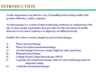
INTRODUCTION Grade separation is an effective way of handling intersecting traffic with greatest efficiency, safety, capacity. An interchange is a system of interconnecting roadways in conjunction with one or more grade separations that provides for the movement of traffic between two or more roadways or highways on different levels. Exhibit 10-1 shows various simple layouts of interchanges. A - Three leg interchange B - Three-level,directional interchange C - An interchange between a major highway and a parkway. D- Diamond interchange E- a Single-Point Urban Interchange (SPUI) F- A partial cloverleaf interchange with two cloverleaf loops and two diagonal ramps. G- A full directional interchange.
WARRANT FOR INTERCHANGES Warrants for Interchanges and Grade Separations Generally the justification of an interchange is difficult. However the following six warrants should be considered when determining if an interchange is justified at a particular site: Design Highways with full control of access between selected Designation terminals. When a freeway is developed, it should be determined that whether each intersecting highway will be terminated, rerouted, or provided with a grade separation or interchange. Reduction of Insufficient capacity at the intersection of heavily traveled Bottleneck or routes; Inability to provide essential capacity with an at-Spot Congestion grade facility
WARRANT FOR INTERCHANGES Safety At grade intersections with a disproportionate rate of Improvement serious crashes. Site Grade separation design is the only option at some sites. Topography Road-User The road-user costs due to delays at congested intersections Benefits are large. Cost-Benefit analysis should be considered. Traffic Volume A tangible warrant. Warrant Others Local roads cannot be terminated for a freeway access to areas not served by frontage roads railroad-highway crossing elimination Heavy pedestrian traffic Bikeway and Pedestrian crossings
COMPARISON INTERSECTING FACILITIES Adaptability of highway grade separations and interchanges Three crossing facilities, at-grade intersections, highway grade separations without ramps, and interchanges are overlapping each other in terms of their suitability. Traffic and Operation Intersections through traffic suffers. Left turning movements suffers Interchanges through traffic are minimally affected. Left turn movements free of interference. Site Conditions Two-level nature of an interchange is Type of Highway and generally a disadvantage with respect to Intersecting Facility appearance and may block the driver’s view of the landscape.
ACCESS SEPARATIONS AND CONTROL Access separations and control on the crossroad at intersections should be considered at the initial design of the interchanges. To ensure efficient operations along the crossroad at an interchange, adequate lengths of access control should be part of the overall design of an interchange. See Exhibit 10-2
GRADE SEPARATION STRUCTURES Types of separation structures Deck type, through and partial through Truss bridges may be used when the spans are long and the elevation difference between roadways is limited Collaborations between the bridge and highway engineers throughout the various stages of planning and design can provide excellent results Overpass needs lateral and vertical clearance . All piers and abutment walls should offset from the traveled way.
GRADE SEPARATION STRUCTURES Overpass Versus Underpass Roadways There are three categories of factors that help designers to determine an overpass or a underpass for a highway: Influence of topography predominates and the design should be closely fitted in Topography does not favor any one arrangement Alignment and grade line controls of one highway predominate and the design should accommodate that highway’s alignment instead of the site topography There are 15 detailed guidelines available on Page 763-764.
GRADE SEPARATION STRUCTURES Structure Widths The clear width on bridges should preferably be as wide as the approach roadway in order to give drivers a sense of openness and continuity.
GRADE SEPARATION STRUCTURES Underpass Roadways Lateral For each underpass, type of structure, dimensional layout, load, Clearance foundation, and general site needs for the bridge are the factors to be considered. Here only dimensional details such as lateral clearances and vertical clearance are discussed here. Exhibit 10-6 - minimum lateral clearances at underpass. The minimum lateral clearance from the ETW to the face of the protective barrier should be the normal shoulder width. Median Clearance Divided Highways: 4 lane 3.0 m 1.2 m 6 lane 6.6 m 3.0 m Vertical The recommended minimum vertical clearance is 4.4 m and the Clearance desirable vertical clearance is 5.0 m.
GRADE SEPARATION STRUCTURES Overpass Roadways The roadway dimensional design of an overpass or other bridge should be the same as that of basic roadway. The primary dimensional design elements for highway designers are bridge railings, lateral clearances, medians. Bridge Bridge railings should be designed to accommodate the design Railing vehicles on the structure under the design impact conditions. Lateral On overpass structures, the full width of the approach roadway Clearance should be provided. 0.6 m should be provided between the longitudinal barrier and the outer edge of the surface shoulder. 0.6 m should also be provided for the bridge rail and the outside of the effective shoulder. Median Undivided highways: 30 m bridge 1.2 median flush, no raised median 30 – 120 m bridge engineering judgment 120 + bridge raised median
GRADE SEPARATION STRUCTURES Longitudinal Distance to Attain Grade Separation L = f ( V, roadway gradient, amount of rise or fall) Exhibit 10-8 shows the relationships among these factors.
GRADE SEPARATION STRUCTURES Grade Separations without Ramps Many cases are available to build grade separations without the provision of ramps. Low traffic volumes on the crossroad can not justify for provision of ramps. Although sufficient traffic volume, ramps cannot be provided because interchanges could be so close to each other, the crossroad traffic have interference with large highway traffic volumes, and safety and mobility are the concerns.
GRADE SEPARATION STRUCTURES Interchanges There are many interchange configurations available to accommodate turning movements at a grade separation. The type of configuration is f (number of intersection legs, expected volumes of through and turning movements, type of truck traffic, and topography, etc.) Three-Leg Designs An intersection with three intersecting legs consists of one or more highway grade separations and one-way roadways for all traffic movements. Exhibit 10-9 shows three examples of three-leg interchanges. The left- turn movements decide the location of the loop. Exhibit10-9 C is not commonly used.
GRADE SEPARATION STRUCTURES Interchanges Four-Leg Designs have one of the five configurations: ramps in one quadrant, diamond interchanges, single-point urban interchange, full or partial cloverleaf and interchanges with direct and semi direct connections. Ramps in one Suitable for low traffic volumes. Limited use at the quadrant intersection of a scenic parkway and a State or county two-lane highway where turning movements are light. Diamond Applied in both rural and urban areas. Common Interchanges and simplest interchanges. A median should be provided on the crossroad to facilitate proper channelization and avoid wrong-way entry from the crossroad.
GRADE SEPARATION STRUCTURES Interchanges Diamond Exhibits 10-16 and 10-17 show examples of diamond Interchanges interchanges. When the front roads are involved, the ramps should be at least 100 m from the crossroad to build up weaving length and space for vehicle storage. Single-Point The primary features of a SPUI are that all four Urban turning moves are controlled by a single traffic signal Interchanges and opposing LT operate to left of each other. SPUI offer several advantages. Cost reductions in ROW. A major source of traffic conflict eliminated. Delay reduction. Disadvantages: Construction costs with bridges Long path for LT through the intersection. A skew angle


