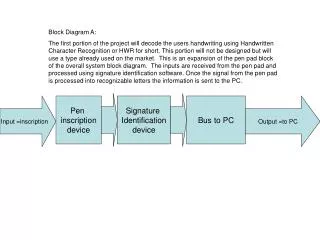

Input =inscription
E N D
Presentation Transcript
Block Diagram A: The first portion of the project will decode the users handwriting using Handwritten Character Recognition or HWR for short. This portion will not be designed but will use a type already used on the market. This is an expansion of the pen pad block of the overall system block diagram. The inputs are received from the pen pad and processed using signature identification software. Once the signal from the pen pad is processed into recognizable letters the information is sent to the PC. Input =inscription Pen inscription device Signature Identification device Bus to PC Output =to PC
Block Diagram B: This Block diagram is for the programming used with the PC. In conjunction with this diagram, a flow chart is shown in Flow chart A. This diagram is the expanded block diagram of the PC block from the main block diagram. The enter/delete input to the port mapping block is to start character mapping /clear (restart) mapping. The mapped character are then translated to movements to be made by the motors (for each character). These movements are sent to the microcontroller. Output = to Microcontroller Input =bus from PC Port Mapping of Characters Description Of motor Movement To Microcontroller device Input= Enter Or Delete Button
Block Diagram C: This is a block diagram of what will be going on with the microcontroller. The inputs to the “PC + Feedback” block comes from the PC as signals that have gone through the handwriting recognition software. These signals are to be translated into movements to be made by the motors. The feedback controller will be located in the Microcontroller as it will change the output of the Microcontroller’s turning of the knobs of the Etch-A-Sketch®. Input =from PC PC + Feedback = current knob turning Output=To Motors Protection Circuitry
Block Diagram D: This block diagrams input comes from the microcontroller to the output being the turning of the Etch-A-Sketch® knobs and consequently drawing a word onto the screen. The H-Bridge turns the knobs both ways for each separate knob and also for turning over the EAS. Input=Signal from Protection circuitry H-Bridge Knobs and Turn over switch Output = written word display
Start Definitions to flow chart blocks Flow Chart A: Shows main program flow chart with definitions. Checks is new data is available Call Data Checker This is only if the device does not do this itself. This is extremely difficult and would rather not be attempted. Call Character Recog Check characters then change to port map of cursive. Map change Connect cursive letters together to form a connected word. Check Space connection Load to microcontroller, either bitmap or line directions. Load to output End
Bradley University ECE Department EE451 – Sr. Capstone Project I CNC Etch-A-Sketch ® Block Diagram 10/22/04 Team Members: Robert Lodesky Arnold Bynum Advisors: Dr. Irwin Mr. Sanchez Main Block Diagram This main block diagram can also be seen in the Functional Description. This is an overall system block diagram for the computer network Controlled Etch-A-Sketch ® (CNC EAS). The pen pad and the keypad (block diagram A) are the two main inputs to the system to be processed (Flow Chart A) by the PC (block diagram B) and the microcontroller (block diagram C). The processed signals are sent to the motors (block diagram D) which will turn the knobs on the EAS. There is only one mode of operation, one means of placing a written word on the EAS. Pen Pad PC Micro Controller Motors Etch-A- Sketch® Key Pad