Kicker Magnet System
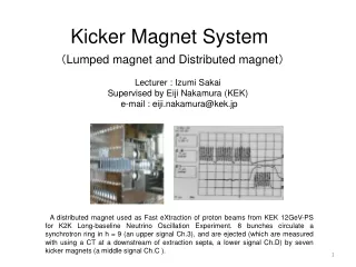
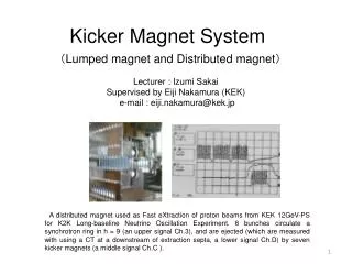
Kicker Magnet System. ( Lumped magnet and Distributed magnet ). Lecturer : Izumi Sakai Supervised by Eiji Nakamura (KEK) e-mail : eiji.nakamura@kek.jp.

Kicker Magnet System
E N D
Presentation Transcript
Kicker Magnet System (Lumped magnet and Distributed magnet) Lecturer : Izumi Sakai Supervised by Eiji Nakamura (KEK) e-mail : eiji.nakamura@kek.jp A distributed magnet used as Fast eXtraction of proton beams from KEK 12GeV-PS for K2K Long-baseline Neutrino Oscillation Experiment. 8 bunches circulate a synchrotron ring in h = 9 (an upper signal Ch.3), and are ejected (which are measured with using a CT at a downstream of extraction septa, a lower signal Ch.D) by seven kicker magnets (a middle signal Ch.C ).
Contents (A) Introduction [1] Field Requirements for Beam Handling [2] Classification by Field Structure [3] Transmission Theory (B) Magnet [1] Lumped type and Distributed Delay Line type [2] Simulation for multi-stage ladder circuit [3] Delay Line Structure (C) Power Supply [1] Fundamental Elements [2] Charger [3] Pulse Forming [4] Switching Devices for High Voltage and Large Current Pulse (D) Total System and Surroundings [1] Outgas and Vacuum System [2] Beam Coupling Impedance, Cooling system for Heat-up by Beam Induced Field (E) Trials Now (F) Key terms to develop in future (*) References and Appendices
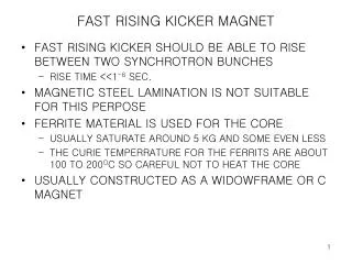
“Electric” or “Magnetic” ? ・Electric kicker Fast response, Simple structure, cheap Field is weak, due to the limitation of break down Magnetic kicker Field is enough, but it is difficult to achieve fast-rise/fall time.
For It is easier to produce 3 kA-pulse than 1 MV-pulse. Magnetic kicker is used for high-energy accelerator. Electric kicker is used for low-energy accelerator.
[A.3] Transmission Theory Resistance load case Inductance load case
Schematic drawing of the ladder-type kicker magnet and it’s equivalent circuit
Fundamental equations for the kicker magnet The response of a ladder-type network for the waves of angular frequency ω is given by next equation. (For steady state) (1) If the unit ladder-type networks are connected infinitely, the wave equation of the circuit is given by, (θ is the phase delay of the unit ladder) (2) (Z is the impedance for angular frequency ω)
By substituting Eq. (2) to Eq. (1), we can get, Here, (3) (4) In the case of 0< ω/ωc<0.5, Then 1< Z/Z0<1.15, ω/ωc~θ/2 For the angular frequency ωis less than 0.5ωc, Impedance is constant and phase delay θis proportional to ω. The series connection of the ladder circuits is considered to be a transmission line with its characteristic impedance of Hence the phase delay θis given as θ=ωτ, and from ω/ωc~θ/2, the phase delay per unit section is given as,
The rise time of the Kicker magnet is given by Where the Tr is the rise time of the PFN. Td is the propagation time in the kicker magnet. Where the “n” is the number of unit ladder in the kicker magnet
[B.2] Simulation for multi-stage ladder circuit Parameters of Model Kicker System for simulation
(1) Most Simple Excitation Equivalent Circuit Forward Pulse Electric potential at the input of a magnet Excitation current Integrated magnetic field
Four stage CL ladder Ten stage CL ladder (C/2)- (CL)-…-(CL)-(C/2)//R) * The last case is for (C/2) – (L) – (C/2) ladder. It is almost same as CL ladder for a low frequency, but is different for a fast step pulse
Practical Limit of Distribution Field quality improves for a large stage number, but it is finite for the following reasons in a practical case. 1. Electric discharge and insulation Strong electric field induces break down over 100 kV/cm, roughly, so unit length and each curvature of edge of materials should be larger than 2.5 mm. Ceramic coating or other technique is used for such a protection. 2. Deterioration of Integrated Flux It is necessary to share space for non-magnetic material to form a capacitance. ※ It is usual to decide unit length about 2 ~ 3 cm.
[B.3] Delay Line Structure Capacitance of air gap between parallel plates is used. It is possible to apply ceramic capacitors, instead of air gaps.
A distance of each cell is limited by the electric insulation, 10 ~ 100kV/cm.
Corner treatment and Ceramic Coating on metal plates are used for suppression of breakdown due to an electric field concentration.
[C.1] Fundamental Elements Typical Requirements: Output Voltage 10 kV ~ 50 kV Output Current 1 kA ~ 10 kA Repetition Rate 1 pps ~ 1 kpps * “pps” means “pulses per second”. Averaged Power ~ 10 kW * It is small in comparison with other magnets for accelerators. Coaxial Cables
[C.2] Charger <a> DC charging: it is stable and cheap, but is limited to use for a low repetition with a large power loss. <b> Resonant charging: an electric efficiency is good, but a step-up transformer is required. <c> Command charging; inverter, … : an electric efficiency and feasibility are good. <a> <b> <c>
[C.3] Pulse Forming <Examples> (i) Simple capacitor case (ii) Pulse Forming Line (PFL) High Voltage coaxial cables and Coaxial tubes, which are filled with dielectric materials; pure water, BaTiO3, etc., are popular as PFL (iii) Pulse Forming Network (PFN) Ringing appears.
[C.4] Switching Devices for High Voltage and Large Current Pulse “Thyratron” is most popular for kicker magnet system, because simple one-device system can produce high voltage large current pulses at fast response. Trials using semi-conductor elements have been carried out.
[D.1] Outgas and Vacuum system If a high field with fast rise is required, a kicker magnet should be installed in vacuum. Ferrite materials are porous with impurities, put them out for a long time, and then deteriorate vacuum quality.
[D.2] Beam Coupling Impedance, Cooling system for Heat-up by Beam Induced Field Heat-up problem is raised in case of high beam current. Cooling systems are required for vacuum ducts, metal materials, … .
[E]Trials Now ! Various trials are being carried out. Some of those are shown here.
[F] Key terms to develop in future “How Fast and How Large Field” can you achieve ?! ~ Examples to develop ~ [a] Power Supply ~ Pulse Power Engineering Techniques ~ (a.1) Charger: high power, high efficiency, … . (a.2) Pulse Forming Devices. Pulse Forming Network. Pulse Forming Line/Tube with using dielectric materials. PE, BaTiO3, pure water, … . Improvement with using Impulse excitation. (a.3) Switches New method for Vacuum tube or Gas-filled tube. Semiconductor.
[b] Magnet (b.1) Optimization of magnet structure. (b.2) Finite distributed magnet for perfect matching of impedance. (b.3) Non-magnetic material magnet. (b.4) Q-, Sext.-, and non-linear magnets for beam injection at electron storage rings. (b.5) High field magnet with using a non-linear characteristic of materials. (b.6) Low beam coupling magnet and its measurement method. (b.7) Investigation and Modeling of Transient Characteristics of materials at fast response and high field. (b.8) BL measurement method: there is no reliable and accurate method to measure higher performance than conventional kickers now. [c] Total Systems and the others (c.1) Vacuum system and Suppression of outgas, unfavorable discharge: double layer vacuum field, insulation techniques. (c.2) Low Level Control system, which enables various outputs of kicker fields. (c.3) New Injection/Ejection Scheme. (c.4) Modeling and Simulation of Fast response near a light velocity. Time dominant 3-D, Formulation, … .
References [1] D. Fiander: “Hardware for a Full Aperture Kicker System for the CPS,” US Part. Accel. Conf. Chicago, 1971. CERN/MPS/SR71-5. [2] Takata, Koji et al.: “Full Aperture Kicker Magnets for KEK Proton Synchrotron,” KEK-PrePrint KEK–76–21 (1976). [3] T. Oki: “The bridged-T network lumped kicker: A novel fast magnetic kicker system for a compact synchrotron,” Nucl. Instr. and Meth. A 607 (2009) 489. [4] < http://psdata.web.cern.ch/psdata/www/Kickers/psparam.htm >. [5] < http://ps-div.web.cern.ch/ps-div/LHC-PS/LHC-PS.html >. [6] D. Neuffer: “Injection and/or Extraction and a Ring Cooler,” Nucl. Instr. and Meth. A 503 (2003) 374-376. [7] B. I. Grishanov et al.: “Very fast kicker with high repetition rate for accelerator applications,” Nucl. Instr. and Meth. A 396 (1997) 28-34. [8] D. Anicic et al.: “A fast kicker magnet for the PSI 600 MeV proton beam to the PSI ultra-cold neutron source,” Nucl. Instr. and Meth. A 541 (2005) 598-609. [9] Efstratios Efstathiadis et al.: “A fast non-ferric kicker for the muon (g-2) experiment,” Nucl. Instr. and Meth. A 496 (2003) 8-25. [10] L. J. Lindgren et al.: “Fast Kicker Magnet System,” Nucl. Instr. and Meth. 214 (1983) 175-178. [11] Gerd Stange: “A new delay-line kicker with capacitive loading sandwiches,” Nucl. Instr. and Meth. A 300 (1991) 425-430. [12] M. Kikuchi et al.: “Beam-transport system of KEKB,” Nucl. Instr. and Meth. A 499 (2003) 8-23. [13] T. Mitsuhashi et al.: “A Design of the Injection Scheme and a Construction of Model Kicker Magnet for the High Brilliance Lattice of the Photon Factory,” Proceedings of 10th Symp. On Accelerator Sci. Tech. (JAERI-Conf.95-021), 1995, p.94. [14] Y. Ishi et al.: “High field, high repetition rate kicker,” Nucl. Instr. and Meth. A 472 (2001) 639-642. [15] Tomohiro Ohkawa et al.: “Development of the kicker magnet for muses,” Nucl. Instr. and Meth. A 547 (2005) 287-293. [16] W. Jiang, et al.: “Compact Solid-State Switched Pulsed Power and Its Application,” Proceedings of the IEEE, Vol. 92, No. 7, July 2004, 1180-1196. [17] W. Zhang, et al.: “Pulsed Power Applications in High Intensity Proton,” Proceedings of 2005 Particle Accelerator Conference, Knoxville, Tennessee, USA (2005) 568-572.
[18] E. Nakamura, et al.: “Injection/Extraction Beam Dump Kicker Magnet Systems for MR of J-PARC,” Proceedings of the 4th Annual Meeting of Particle Accelerator Society of Japan and the 32nd Linear Accelerator Meeting in Japan, Wako, Japan, August 1-3, (2007) 787-789. [19] E. Nakamura, et al.: “A Modification Plan of the KEK 500 MeV Booster to an all ion accelerators (an injector-free synchrotron),” Proceedings of 2007 Particle Accelerator Conference, Albuquerque, New Mexico, USA, June 21-29 (2007) 1492. [20] Tanuja S. Dixit et al.: “Induction acceleration scenario from an extremely low energy in the KEK all-ion accelerator,” Nucl. Instr. and Meth. A 602 (2009) 326-336. [21] V. D. Shiltsev: “Beam-beam kicker for superfast bunch handling,” Nucl. Instr. and Meth. A 374 (1996) 137-143. [22] H. Barkhausen: Phys. Z. 20 (1919) 401. [23] M. Konuma: “Magnetic Materials,” Kohgaku-Tosho Co., Ltd., 1996, ISBN4-7692-0355-1 C3055 (in Japanese). [24] G. Nassibian and F. Sachere: “Method for Measuring Transverse Coupling Impedances in Circular Accelerator,” Nuclear Instruments and Methods 159 (1979) 21-27. [25] H. Hahn and A. Ratti: “On the Low-Frequency Coupling Impedance of Transmission Line Kickers,” AD/RHIC/RD-111 of BNL, March, 1997. [26] H. Hahn: “Equivalent Circuit Analysis of the RHIC Injection Kickers,” AD/RHIC/RD-112 of BNL, April, 1997. [27] E. Nakamura, et al.: “Beam Injection/Extraction for All-ion Accelerator (AIA),” Proceedings of the 9th Accelerator and Related Technology for Application, TIT, Tokyo, Japan, June 21-22, 2007, 21p6. [28] E. Nakamura, et al.: “PoP-experiments of the all-ion accelerator,” Proceedings of 2007 Fall Meeting of the Atomic Energy Society of Japan, Fukuoka, Japan, Sept. 27-29, (2007) 135 (in Japanese). [29] < http://www-accps.kek.jp/staff/BEAM-Group/Kicker-Group/index.html >. [30] E. Nakamura: “Fast-rise high-field kicker magnet operating in saturation,” Nucl. Instr. and Meth. A (to be published).