Mechanical Spine Test Platform P10007
300 likes | 322 Vues
Mechanical Spine Test Platform P10007. DETAILED DESIGN REVIEW GROUP MEMBERS : Irma Bocova Rob Bowman Phetphouvanh “Awt” Phommahaxay Kyle Pilote Jeff Rebmann Chris Rowles Faculty Guide : Dr. Elizabeth DeBartolo November 6 th , 2009. Agenda. Desired Outcomes – 11:00am

Mechanical Spine Test Platform P10007
E N D
Presentation Transcript
Mechanical Spine Test PlatformP10007 DETAILED DESIGN REVIEW GROUP MEMBERS: Irma Bocova Rob Bowman Phetphouvanh “Awt” Phommahaxay Kyle Pilote Jeff Rebmann Chris Rowles Faculty Guide: Dr. Elizabeth DeBartolo November 6th , 2009
Agenda • Desired Outcomes – 11:00am • Project Background – 11:05am • Mechanical Design – 11:15am • Drawings/Schematics • Feasibility Calculations • Electrical Design – 11:35pm • Selection • Accelerometer issues • MicroStrain 3DM sensor • Output Design – 11:55pm • Bill of Materials – 12:10pm • Risks/Feasibility – 12:20pm • Preliminary Test Plan – 12:40pm • Next Steps
Desired Outcomes of Review • Receive input on selected concept • Identify and discuss key risks: • Sensor interference • Discuss LabVIEW
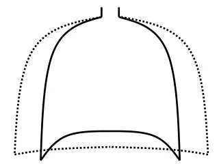
Mission Statement • The intent of this project is to design and build a test platform that will mimic the actions of a human spine. This design will incorporate movements in three dimensions, while being able to independently measure the angles and linear adjustments. The purpose of developing this platform is to validate the data from an existing measuring device in use at the Nazareth Physical Therapy Clinic.
Project Description • Project Title: Mechanical Spine Test Platform • Primary Customer • Dr. Sara Gombatto • Professor at Nazareth College of Physical Therapy • Dr. JJ Mowder-Tinney • Director of Clinical Education Nazareth College Department of Physical Therapy • Physical therapy patients • Secondary Opportunities • Further spinal iterations
Background/Application • Nazareth Physical Therapy Clinic motion capture system • Allows motion capture of PT patients in order to track progress • Validation of existing motion captures • Focus on spinal segments • Secondary Application: • Portable Motion Tracking System calibration Source: http://seneludens.utdallas.edu/images/mocap.jpg
Customer Needs • Three tiered approach to group needs and limit scope • Base Plan • Aggressive • Outstanding • Example Need: Must be moveable in distinct segments • Base Plan – Two distinct sections (Lower & Upper Lumbar) • Aggressive – Three distinct sections (Lower & Upper Lumbar, Thoracic) • Outstanding – Divide Thoracic segment into multiple segments
Engineering Specifications • Correspond to highest ranked Customer Needs:
Electrical Selection Analog Devices- Adxl202 accelerometer MicroStrain’s- 3DM
Microstrain 3DM • Magnetometers and accelerometers are used to compute pitch, roll, and yaw. • Output provides raw magnetic field and accelerometer outputs, or pitch, roll, and yaw outputs. • Communication through a serial port.
Calculations The sensor outputs the orientation information in 3 different forms: Euler Angles Quaternion 3x3 Rotational Matrix Orientation in the form of Rotational Matrix is given in the form: Orientation in the form of Euler Angles is derived from the rotational matrix. (Calculated using “aircraft”) Elevation (pitch) Bank (roll) Heading (yaw)
Calculations The rotational matrix can be calculated from a set of Euler angles using the equation below:
Process Estimated times are given for each task in the process. This allows for an estimated total process time as well as expected maximum and minimum times.
LabVIEW Interface will allow user to see the angular displacement of the pitch, roll, and yaw of the Lower Lumbar and Upper Lumbar segments based on output from the sensors Customer will download free LabVIEW Run-Time Engine Output will run as an executable program application User can only use the application, not change coding
Next Steps… • Implement action items from Detailed Design Review • Actively test ball joint drilling • Order long lead time parts • Update EDGE with latest information • Create MSD II schedule