Global Design Effort: Summary Report on ILC Physics Baseline Configuration
This report outlines the design and plan of the International Linear Collider (ILC) project, detailing parameters, costs, and progress. It includes the Reference Design Report, value assessments, and the implementation timeline.

Global Design Effort: Summary Report on ILC Physics Baseline Configuration
E N D
Presentation Transcript
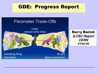
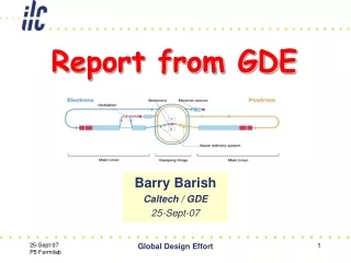
Report from GDE Barry Barish Caltech / GDE 25-Sept-07 Global Design Effort
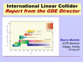
2005 2006 2007 2008 2009 2010 Global Design Effort Project LHC Physics Baseline configuration Reference Design The GDE Plan and Schedule Engineering Design ILC R&D Program Expression of Interest to Host International Mgmt Global Design Effort
Parameters for the ILC • Ecm adjustable from 200 – 500 GeV • Luminosity ∫Ldt = 500 fb-1 in 4 years • Ability to scan between 200 and 500 GeV • Energy stability and precision below 0.1% • Electron polarization of at least 80% • The machine must be upgradeable to 1 TeV Global Design Effort
Designing a Linear Collider Superconducting RF Main Linac Global Design Effort
RDR ILC Schematic • 11km SC linacs operating at 31.5 MV/m for 500 GeV • Centralized injector • Circular damping rings for electrons and positrons • Undulator-based positron source • Single IR with 14 mrad crossing angle • Dual tunnel configuration for safety and availability Global Design Effort
RDR Design Parameters Global Design Effort
RDR Design & “Value” Costs Summary RDR “Value” Costs Total Value Cost (FY07) 4.80 B ILC Units Shared + 1.82 B Units Site Specific + 14.1 K person-years (“explicit” labor = 24.0 M person-hrs @ 1,700 hrs/yr) 1 ILC Unit = $ 1 (2007) • The reference design was “frozen” as of 1-Dec-06 for the purpose of producing the RDR, including costs. • It is important to recognize this is a snapshot and the design will continue to evolve, due to results of the R&D, accelerator studies and value engineering • The value costs have already been reviewed twice • 3 day “internal review” in Dec • ILCSC MAC review in Jan • Σ Value = 6.62 B ILC Units Global Design Effort 7
Assessment of the RDR • Reviews (5 major international reviews + regional) • The Design:“The MAC applauds that considerable evolution of the design was achieved … the performance driven baseline configuration was successfully converted into a cost conscious design.” • The R&D Plan: “The committee endorses the approach of collecting R&D items as proposed by the collaborators, categorizing them, prioritizing them, and seeking contact with funding agencies to provide guidelines for funding. • International Cost Review (Orsay):Supports the costing methodology; considered the costing conservative in that they identify opportunities for cost savings; etc. Global Design Effort
RDR Complete • Reference Design Report (4 volumes) Physics at the ILC Executive Summary Detectors Accelerator Global Design Effort
RDR Complete • Companion Document (printed & website in October) Gateway Document for broad circulation, including translations Global Design Effort
Prepare to Propose ILC Construction • ILC Engineering Design • We have a solid design concept in the reference design, but it is immature and needs engineering designs, value engineering, supporting R&D and industrialization. • GDE has been reorganized around a GDE Project Management Office to reach this goal • Marc Ross, Nick Walker and Akira Yamamoto • Central management being given the authority to set priorities and direct the work • Resources for the engineering design and associated R&D appears feasible (FALC will concur on work packages) • Investments will be made toward Industrialization and siting • Anticipate LHC results in about 2010. We plan to be ready whenever the physics motivation is in place! Global Design Effort
GDE EDR Organizational Structures FALC ICFA/ILCSC • Project Management • 3 PMs • Internal Reviews • FALC - work packages Global Design Effort
ILC Work Package Agreement Global Work Package Definition & Resources FALC Resource Group Concurrence Statement of Work for the Global Work Package & Resources Xn MOU between GDE and Participating Institution on the Global Work Package Regional Director Concurrence Global Design Effort
Supporting R&D & Regional Programs • Global R&D • Organized around task forces to achieve milestones linked to EDR schedule • S0 task force - globally coordinated program to demonstrate gradient for EDR by 2009 • S2 task force – RF unit test and string tests by construction • S3 task force – Electron Cloud tests to establish mitigation and verify one damping ring is sufficient. • Regional Preparations • Siting preparations – prepare to bid to host • Developing regional expertise on SCRF • Regionally based infrastructure and facilities • Industrialization Global Design Effort
Technically Driven Timeline 2006 2010 2014 2018 Engineer Design Construction Startup BCD Begin Const End Const RDR EDR Detector Construct Detector Install Siting Plan being Developed Site Select Site Prep Pre-Operations All regions ~ 5 yrs R & D -- Industrialization System Tests & XFEL Gradient Cryomodule Full Production August e-Cloud Global Design Effort
Reference Design and Plan Producing Cavities Cavity Shape single cells Obtaining Gradient Global Design Effort
Cavity Gradient - Results Global Design Effort
Module Test – Results DESY Global Design Effort
Cost Benefit: S0 Gradient R&D • Optimistic scenario with final batch + tightloop • Costs 36 MILCU for the R&D • Gives highest confidence about the gradient distribution • This needs to be compared to: • A reduction of the average gradient for the ILC from design of 31.5 to 28 MV/m • ~ 600 MILCU Global Design Effort
Cryomodules TESLA cryomodule 4th generation prototype ILC cryomodule Global Design Effort
S2 String Tests • Build 1 RF unit (3 cryomodules + 1 Klystron) • What gradient spread can be handled by LLRF system? • Test with and without beam loading. • For heating due to high frequency high order modes • Amplitude and phase stability. • Static and dynamic heat loads. • Purpose is to test • Reliability; Dark current; Degradation or other weaknesses • Second phase string test needed before construction to verify modules for the ILC. Global Design Effort
S2 String Tests • Risk with no string tests Build ~1.5 BILCU of cryomodules, then discover a design flaw. • Schedule/Cost risk -- fixing them could take years and cost > 20% of the original cost. • Categorize as medium risk (25%) Risk*Cost ~75 MILCU, plus schedule loss (years). • Risk would be higher 50-100% if not for the Tesla Test Facility. • The planned string tests (One RF Unit) ~ $50 MILCU. Global Design Effort
The Main Linac • Developing capability to construct in all three regions • Facilities developed regionally • Industrialization; assembly; testing Global Design Effort
Electron Cloud Mitigation • Low Emittance Damping Ring • Ensure the e- cloud won’t blow up the e+ beam emittance. • Baseline -- Two positron damping rings – alternate bunches. • RDR – Change to one damping ring; move to central injectors; share tunnel • Assumed mitigation of electron cloud successful • R&D Program • Simulations (cheap and encouraged making change) • Test vacuum pipe coatings, grooved chambers, and clearing electrodes effect on ecloud buildup • Do above in ILC style wigglers with low emittance beam to minimize the extrapolation to the ILC. Global Design Effort
E Cloud – Simulation Results SLAC Global Design Effort
Cost Benefit: S3 Electron Cloud R&D • R&D for Electron Cloud • High risk (~50%) that we must build a second e+ damping ring at a cost of 200 MILCU. (Cost risk = 100 MILCU) • KEK-B and/or CESR R&D test program will involve dedicated use of the whole ring. The scale of R&D cost ~ 20-30 MILCU. Global Design Effort
Main Linac Double Tunnel • Three RF/cable penetrations every rf unit • Safety crossovers every 500 m • 34 kV power distribution Global Design Effort
Conventional Facilities 72.5 km tunnels ~ 100-150 meters underground 13 major shafts > 9 meter diameter 443 K cu. m. underground excavation: caverns, alcoves, halls 92 surface “buildings”, 52.7 K sq. meters = 567 K sq-ft total Global Design Effort
Reference Design and Plan Making Positrons 6km Damping Ring 10MW Klystrons Beam Delivery and Interaction Point Global Design Effort
Technically Driven Timeline 2006 2010 2014 2018 Engineer Design Construction Startup BCD Begin Const End Const RDR EDR August Global Design Effort
Civil Construction Timeline Global Design Effort
On-surface Detector AssemblyCMS approach • CMS assembly approach: • Assembled on the surface in parallel with underground work • Allows pre-commissioning before lowering • Lowering using dedicated heavy lifting equipment • Potential for big time saving • Reduces size of required underground hall Global Design Effort
Technically Driven Timeline 2006 2010 2014 2018 Engineer Design Construction Startup BCD Begin Const End Const RDR EDR Siting Plan being Developed Site Select Site Prep All regions require ~ 5 yrs August Global Design Effort
Preconstruction Plan: Fermilab Central Area fits inside the Fermilab boundary ~ Boundary of Fermilab Site Characterization of the Central Area can be done ~ 5.5 km ~ 5.5 km Global Design Effort
Technically Driven Timeline 2006 2010 2014 2018 Engineer Design Construction Startup BCD Begin Const End Const RDR EDR Siting Plan being Developed Site Select Site Prep All regions ~ 5 yrs R & D -- Industrialization August Global Design Effort
Schedule in Graphical Form 2009 2012 2015 2018 Construction Schedule Cryomodule Production RF System Tests Global Design Effort
Technically Driven Timeline 2006 2010 2014 2018 Engineer Design Construction Startup BCD Begin Const End Const RDR EDR Detector Construct Detector Install Siting Plan being Developed Site Select Site Prep All regions ~ 5 yrs R & D -- Industrialization System Tests & XFEL Gradient Cryomodule Full Production August e-Cloud Global Design Effort
Detector Concepts Global Design Effort
Detector Performance Goals • ILC detector performance requirements and comparison to the LHC detectors: ○ Inner vertex layer ~ 3-6 times closer to IP ○ Vertex pixel size ~ 30 times smaller ○ Vertex detector layer ~ 30 times thinner Impact param resolution Δd = 5 [μm] + 10 [μm] / (p[GeV] sin 3/2θ) ○ Material in the tracker ~ 30 times less ○ Track momentum resolution ~ 10 times better Momentum resolution Δp / p2 = 5 x 10⁻⁵ [GeV-1] central region Δp / p2 = 3 x 10⁻⁵ [GeV-1] forward region ○ Granularity of EM calorimeter ~ 200 times better Jet energy resolution ΔEjet / Ejet = 0.3 /√Ejet Forward Hermeticity down to θ = 5-10 [mrad] Global Design Effort
Concept: one IR - two detectors detector B The concept is evolving and details being worked out may be accessible during run detector A accessible during run Platform for electronic and services (~10*8*8m). Shielded (~0.5m of concrete) from five sides. Moves with detector. Also provide vibration isolation. Global Design Effort
Technically Driven Timeline 2006 2010 2014 2018 Engineer Design Construction Startup BCD Begin Const End Const RDR EDR Detector Construct Detector Install Siting Plan being Developed Site Select Site Prep Pre-Operations All regions ~ 5 yrs R & D -- Industrialization System Tests & XFEL Gradient Cryomodule Full Production August e-Cloud Global Design Effort
Conclusions • The ILC design is proceeding toward an engineering design (EDR) in 2010. • Be ready to propose construction when LHC results justify! • R&D program is being globally coordinated to determine gradient, electron cloud, industrialization, mass production. • Overall priorities are being set for risk reduction • There are regional programs to develop SCRF expertise and prepare to bid to host • Detector R&D/design also very important to be able to fully exploit the ILC (e.g. spatial & energy resolution) • Appointment of Research Director - S Yamada for better coordination, better regional balance • LOIs in one year Global Design Effort