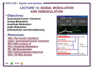
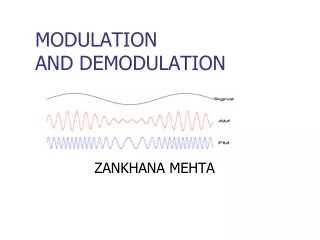
MODULATION AND DEMODULATION
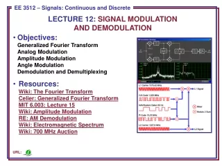
This text explains modulation, where a message signal controls a carrier signal to convey information through modulation techniques like AM, FM, PM, PCM. It also covers digital transmission advantages and pulse modulation methods.

MODULATION AND DEMODULATION
E N D
Presentation Transcript
MODULATION AND DEMODULATION ZANKHANA MEHTA
Basic terms related to Modulation? In modulation, a message signal, which contains the information is used to control the parameters of a carrier signal, so as to impress the information onto the carrier. The Messages The message or modulating signal may be either: analogue – denoted by m(t) digital – denoted by d(t) – i.e. sequences of 1's and 0's The message signal could also be a multilevel signal, rather than binary; this is not considered further at this stage. The Carrier The carrier could be a 'sine wave' or a 'pulse train'. Consider a 'sine wave' carrier:
Communication systems • Analog Modulation • AM • FM • PM • Digital Modulation • PAM • PPM • PWM • PCM
Amplitude modulation is the process of varying the amplitude of a carrier wave in proportion to the amplitude of a baseband signal. The frequency of the carrier remains constant The modulating Signal become envelop to the carrier. The bandwidth of the modulated signal is equal to twice the bandwidth of the modulating signal Since on both sides of the carrier freq. fc, the spectrum is identical, we can discard one half, thus requiring a smaller bandwidth for transmission. Amplitude Modulation
Note The total bandwidth required for AM can be determined from the bandwidth of the audio signal: BAM = 2B.
The modulating signal changes the freq. fc of the carrier signal The bandwidth for FM is high It is approx. 10x the signal frequency Frequency Modulation
Note The total bandwidth required for FM can be determined from the bandwidth of the audio signal: BFM = 2(1 + β)B. Where is usually 4.
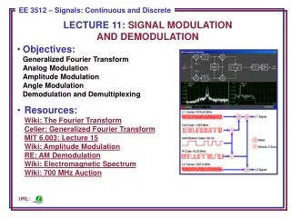
The modulating signal only changes the phase of the carrier signal. The phase change manifests itself as a frequency change but the instantaneous frequency change is proportional to the derivative of the amplitude. The bandwidth is higher than for AM. Phase Modulation (PM)
Note The total bandwidth required for PM can be determined from the bandwidth and maximum amplitude of the modulating signal:BPM = 2(1 + β)B. Where = 2 most often.
Merits of Digital Communication: END • Digital signals are very easy to receive. The receiver has to just detect whether the pulse is low or high. • AM FM signals become corrupted over much short distances as compared to digital signals. In digital signals, the original signal can be reproduced accurately. • The signals lose power as they travel, which is called attenuation. When AM and FM signals are amplified, the noise also get amplified. But the digital signals can be cleaned up to restore the quality and amplified by the regenerators. • The noise may change the shape of the pulses but not the pattern of the pulses. • AM and FM signals can be received by any one by suitable receiver. But digital signals can be coded so that only the person, who is intended for, can receive them. • AM and FM transmitters are ‘real time systems’. I.e. they can be received only at the time of transmission. But digital signals can be stored at the receiving end. • The digital signals can be stored, or used to produce a display on a computer monitor or converted back into analog signal to drive a loud speaker.
PULSE MODULATION • Pulse modulation may be used to transmit analog information, such as continuous speech or data. • It is a system in which continuous waveform are sampled at regular intervals. • Information regarding the signal is transmitted only at the sampling times, together with any synchronizing pulses that may be required. • At the receiver, the original waveform may be reconstructed.
Analog signal is sampled every TS secs. Ts is referred to as the sampling interval. fs = 1/Ts is called the sampling rate or sampling frequency. There are 3 sampling methods: Ideal - an impulse at each sampling instant Natural - a pulse of short width with varying amplitude Flattop - sample and hold, like natural but with single amplitude value Sampling
PULSE MODULATION The process of transmitting signals in the form of pulses (discontinuous signals) by using special techniques. • The Chapter includes: • Pulse Amplitude Modulation • Pulse Width Modulation • Pulse Position Modulation • Pulse Code Modulation
PULSE AMPLITUDE MODULATION • Pulse-amplitude modulation (PAM), is a form of signal modulation where the message information is encoded in the amplitude of a series of signal pulses. • It is an analog pulse modulation scheme in which the amplitudes of a train of carrier pulses are varied according to the sample value of the message signal. • Demodulation is performed by detecting the amplitude level of the carrier at every symbol period
Pulse Amplitude Modulator Analog Signal Amplitude Modulated Pulses
Pulse Width Modulation (PWM): * In this type, the amplitude is maintained constant but the duration or length or width of each pulse is varied in accordance with instantaneous value of the analog signal. * The negative side of the signal is brought to the positive side by adding a fixed d.c. voltage. Analog Signal Width Modulated Pulses
Pulse Position Modulation (PPM): * In this type, the sampled waveform has fixed amplitude and width whereas the position of each pulse is varied as per instantaneous value of the analog signal. * PPM signal is further modification of a PWM signal. It has positive thin pulses (zero time or width) corresponding to the starting edge of a PWM pulse and negative thin pulses corresponding to the ending edge of a pulse. PWM PPM
Pulse Code Modulation (PCM): • Pulse-code modulation (PCM) is a method used to digitaly represent sampled analog signals. It is the standard form of digital audio in computers, digital telephony and other digital audio applications. • In a PCM stream, the amplitude of the analog signal is sampled regularly at uniform intervals, and each sample is quantized to the nearest value within a range of digital steps.
Pulse Code Modulation (PCM) x(t) 3 2 1 0 t Consider the analog Signal x(t).
Pulse Code Modulation (PCM) x[n] 3 2 1 0 n The signal is first sampled
Pulse Code Modulation (PCM) 3 2 1 0 n
Pulse Code Modulation (PCM) 3 2 1 0 n
Pulse Code Modulation (PCM) 3 2 1 0 n Sample
Pulse Code Modulation (PCM) 3 2 1 0 n And Hold
Pulse Code Modulation (PCM) 3 2 1 0 n
Pulse Code Modulation (PCM) Assign Closest Level 3 2 1 0 n
Pulse Code Modulation (PCM) 3 2 1 0 n
Pulse Code Modulation (PCM) 3 2 1 0 n
Pulse Code Modulation (PCM) 3 2 1 0 n
Pulse Code Modulation (PCM) 3 2 1 0 n
Each quantization level corresponds to a unique combination of bits. The analog signal is transmitted/ stored as a stream of bits and reconstructed when required. 3 2 1 0 n
Each quantization level corresponds to a unique combination of bits. The analog signal is transmitted/ stored as a stream of bits and reconstructed when required. 3 2 1 0 n 0 0 0 1 1 1 1 0 0 1 0 0 1 0