Telegrapher ’ s Equations
Learn the key concepts of wave propagation, reflection, phase matching, and power transmission in transmission lines. This resource explores Telegrapher’s Equations, impedance matching, standing wave ratios, power transfer, and applications of transmission lines. Discover how incident and reflected waves cancel out, and delve into impedance matching strategies for optimal performance.

Telegrapher ’ s Equations
E N D
Presentation Transcript
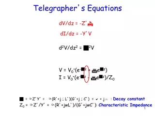
Telegrapher’s Equations dV/dz = -Z’I dI/dz = -Y’V d2V/dz2 = g2V V = V0+(e-gz + Gegz) I = V0+(e-gz - Gegz)/Z0 • = Z’Y’ = (R’+jwL’)(G’+jwC’) = a + jb : Decay constant Z0 = Z’/Y’ = (R’+jwL’)/(G’+jwC’): Characteristic Impedance
Lossless Line R’ = G’ = 0 g =jb = jwL’C’ Z0 = L’/C’ = 377 W in free space (impedance of free space) a=0 (lossless) v = w/b: indep. of frequency (dispersionless) • Dispersionless: undistorted signal • Genl. Condition: R’/G’ = L’/C’
Transmission Line LOAD Reflection at a load Z0 ZL V(z) = V+0(e-jbz + Gejbz) I(z) = V+0(e-jbz - Gejbz)/Z0 V(0)/I(0) = ZL G = (ZL-Z0)/(ZL+Z0) = |G|ejqr ZL=Z0 [(1+G)/(1-G)]
Work backwards to input impedance Zin Z0 ZL Transmission Line LOAD V(z) = V+0(e-jbz + Gejbz) I(z) = V+0(e-jbz - Gejbz)/Z0 V(-l)/I(-l) = Zin Zin=Z0 [(1+Gejbl)/(1-Gejbl)] ie, to get Z(d), G Ge-jbd in ZL formula
Zin Z0 ZL Vin Transmission Line LOAD Set Vin = IinZin = VSZin/(ZS+Zin) = V(-l) = V0+(ejbl + Ge-jbl) gives V0+ Nailing down V0+ Iin ZS VS V(z) = V+0(e-jbz + Gejbz) Why is V(-l)/I(-l) ≠ Zs? Because we haven’t included the source current Iin Iin = VS/(ZS + Zin)
Special Cases: Impedance match. (ZL = Z0) G = 0 No reflection
Special Cases: Short ckt. (ZL = 0) G = -1 Refln. at a hard wall (phase p)
Special Cases: Open Ckt. (ZL = ∞) G = 1 Refln. at a soft wall (phase 0)
Special Cases: Reactive load(ZL: imaginary) • = ejf |G| = 1 Fully reflected, but with intermediate phase (reactive component picked up)
V(z)s for diff cases V(z) = V+0(e-jbz + ejbz) = 2V+0cos(bz) for open ckt V(z) = V+0(e-jbz - ejbz) = 2jV+0sin(bz) for short ckt V(z) = V+0e-jbz for matched load 2|V+0| |V+0| http://www.bessernet.com/Ereflecto/tutorialFrameset.htm
Standing Wave Ratio V(z) = V+0(e-jbz + Gejbz) |V(z)| = V+01 + |G|2 + 2|G|cos(2bz+qr) S = VSWR = |Vmax|/|Vmin| = (1+|G|)/(1-|G|) = 1 for matched load, ∞ for open/short/reactive load CSWR = |Imax|/|Imin| http://www.bessernet.com/Ereflecto/tutorialFrameset.htm
ZS Z0 ZL Transmission Line Applications (Antireflection coating) GL = (ZL-Z0)/(ZL+Z0) ZL=Z0 [(1+GL)/(1-GL)] Zin=Z0 [(1+GLe-2jbl)/(1-GLe-2jbl)]
ZS Z0 ZL Transmission Line • Qr. wave plate (Phase p for reflection to cancel incident) 2. “Bridge” impedance is geometric mean (Depends on product + correct dimensions) Zin=ZS (Zin/Z0) = (ZS/Z0) • ZS = ZL • bl=p/2, l=l/4, Z0 = ZSZL Applications (Antireflection coating) Trick: Looking from Source side, effective impedance of line should be matched with ZS
ZS Z0 ZL Transmission Line Applications (Antireflection coating) Explanation: Consider incident and reflected waves To cancel, reflected wave must • have opposite phase to incident in order to cancel it • be of equal strength as incident wave for complete cancellation Reflected wave has extra phase 2bL relative to incident For condition (a), need 2bL = p, implying 2(2p/l)L=p L = l/4 For condition (b), need ZL/Z0 = Z0/Zs Z0 = ZL.Zs
V = Vacos(wt) I = Iacos(wt+f) T 1 P = ∫ P(t)dt = VaIacos(f) T 0 Power Transfer V(z) = V0(e-jbz + Gejbz) I(z) = V0(e-jbz - Gejbz)/Z0 P(z) = ½ Re[V(z)I*(z)] P(t) = IV = VaIa[cos(2wt+f) + cos(f)] ½ ½ = ½ Re[VI*]
Pi = |V0|2/2Z0 Power Transfer V(z) = V0(e-jbz + Gejbz) I(z) = V0(e-jbz - Gejbz)/Z0 P(z) = ½ Re[V(z)I*(z)] Pt = P(0) = Re[V0(1+|G|ejq)V0*(1-|G|e-jq)/2Z0] = |V0|2(1-|G|2)/2Z0 Power transfer Pt/Pi = 1 - |G|2 (No reflection all power transferred)
Impedance Matching d Z0 Z0 ZL Matching stub Zs Matching network Adjust d so Yin = Y0 + jB cos(bd) = -G, B =[(ZL2-Z02)/(2ZLZ0)]1-G2 Adjust the reactance of the stub so Ys = -jB bd =cot-1(B/Y0)
Summary • Learned key concepts – wave propagation, reflection, phase and impedance matching, power transmission etc • Note that we did not worry about how the waves were created, or what determines the parameters such as C, Z0, L etc. We will learn that in chapters 4-7. • We will encounter these wave properties again when we talk about real EM waves that also reflect, transmit etc at boundaries. But they do so in 3-D, which needs the language of vector algebra.