Download
1 / 24
240 likes | 339 Vues
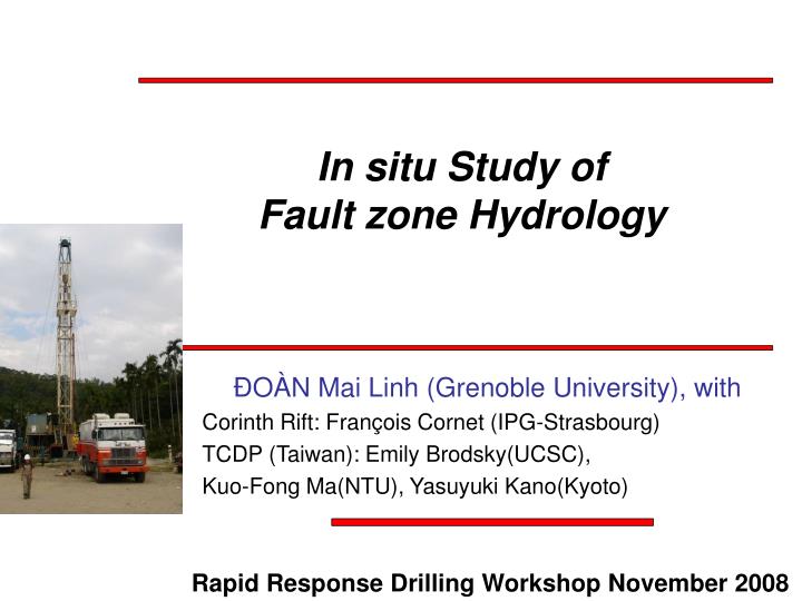
In situ Study of Fault zone Hydrology. ÐOÀN Mai Linh (Grenoble University), with Corinth Rift: François Cornet (IPG-Strasbourg) TCDP (Taiwan): Emily Brodsky(UCSC), Kuo-Fong Ma(NTU), Yasuyuki Kano(Kyoto). Rapid Response Drilling Workshop November 2008. Hydraulic properties of faults.

E N D
In situ Study of Fault zone Hydrology ÐOÀN Mai Linh (Grenoble University), with Corinth Rift: François Cornet (IPG-Strasbourg) TCDP (Taiwan): Emily Brodsky(UCSC), Kuo-Fong Ma(NTU), Yasuyuki Kano(Kyoto) Rapid Response Drilling Workshop November 2008
Hydraulic properties of faults Host rock High pressure reduces effective normal stress and facilitates slip Damage zone Fault core During rupture, hydraulic diffusivity controls pressure buildup Between earthquakes, hydraulic properties control the fault recovery Seismic cycle • We focus on direct in-situ measurements, • which capture: • Mesoscale • Original fluid and confining pressure • Time evolution
2 major methods • Intermittent large scale pumping tests • Permeability • Hint on pressure • Taiwan Chelungpu-Fault Drilling Project • Long term monitoring • Pressure • Poroelastic behavior • Hint on permeability • Corinth Rift Laboratory
Example 1 • AIG10 borehole • in Corinth Rift Laboratory • Long term pore pressure monitoring • Complete poroelastic determination (Earth tides) • Permeability determination (Oceanic tides) Other examples: PBO, PFO (both not in faults)
0.9±0.1MPa karst Corinth Rift Laboratory South North Conglomerates Clays Limestone 0.5±0.1MPa Radiolarites Impermeable fault Limestone
Typical high precision record Pressure Resolution better than 1% Pressure (Bar) UT Time The data is dominated by the karst (?), not the fault Tides are recorded. We get the response of the aquifer to a known input
Pore recording on tides Two effects 1-Poroelastic response of the formation 2- Hydraulic properties of the formation Tides deform the Earth and the formation surrounding the well Water flows to the well to equilibrate the pressure 1 2 In a confined medium this induces variation in pressure
Major results Full poroelastic determination Notably, strain-pressure conversion coefficient BKu=27GPa pore pressure ≈ strainmeter (results independent on the aquifer) Estimate of the hydraulic diffusivity D=20m2/s A value that direct pumping tests were unsuccessful to provide (hypothesis on boundary conditions)
Dynamically triggered event 5 minutes with D=20m2/s 110m Local Fault ? November, 17th 2003 06:43 UTC Drop of 60 Pa (equivalent to 3.5nstr with BKu=27GPa) 30min 5min Doan et Cornet, EPSL, 2007
Lessons learnt from CRL • Do not let your hole open near the fault • -> risk of collapse • -> Artificial fluid flow between compartments • if the fault is a hydraulic barrier • Fluids follow the more permeable path • This conditions monitoring strategy • Here, permeable fault • => Target surrounding aquifers if the fault zone too small • Pore presssure = strainmeter • Problem of boundary conditions • Issues with • Fault permeability -> 2 holes
Example 2 • Taiwan Chelungpu Fault Project • Pumping test • Hydraulic diffusivity and permeability • Rough estimate of pressure Other examples: Nojima (Kitagawa,99)
Chichi earthquake Sept. 21 1999 Mw=7.6 Large movement Small acceleration High fluid pressure ? Is the diffusivity low? (Ma et al. 2003)
Principle of the test Hole A Hole B Diffusivity along the fault Permeability along the fault Perforation 1111m ~1137m Chelungpu fault Perforation 40m
Output data (corrected) D=6×10⁻⁵ m2/s D=7×10⁻⁵ m2/s D=8×10⁻⁵ m2/s
Major results • Weconstrain the hydraulicdiffusivityof the damage zone • D=(7±1)×10-5 m2/s • Thermal pressurization probable • No direct measurement of permeability. • Using lab data and theory for the missing parameters, • k between 10-18m2 and 10-16m2 • M pattern of permeability • Damage zone not so permeable. Premature sealing after 6 yr ? Fault Core < Host rock < Damage Zone 10-21-10-19m2 10-19-10-18m210-18-10-16m2 (Lockner2006) (Chen2005) (Doan et al.2006) Rough overpressure estimate from inflow rate and k between 0.06MPa and 6MPa Not highy pressurized (<20% lithostatic pressure only)
Pratical lessons learnt from TCDP • Borehole completion issues • Leaks everywhere prevented • direct measurement • of pore pressure and permeability • Fluid follows the most permeable path • Leaks and damage zone dominates the hydraulic data • Strategy: direct monitoring of fault (once leaks are eliminated) « Geotechnical model » Fault is a hydraulic conduit Chelungpu fault « Petroleum model » Fault is a hydraulic barrier Corinth Rift Laboratory
Conclusions : Parameters • Direct assessment of • pressure, permeability and hydraulic diffusivity • within active fault zone yielded • by pore pressure monitoring and hydraulic tests. • Parameters • No precise in-situ measurement of pore pressure • The faults studied seems to be not much overpressurized • They are poor fluid conduits. • The results may be fault dependent. • The fault catalogue is still small
Conclusions: Methods • Methods • The methods are complementary • Pumping tests are more spatially resolved • Permanent pore pressure monitoring yields refined time evolution • Dynamic triggering and other transients can be detected • in addition to postseismic healing. • Strategy • Strategy is dependent on fault structure and permeability • « Petroleum model » • Fault is a hydraulic barrier • surrounding pore pressure • « strainmeter » • « Geotechnical model » • Fault is a hydraulic conduit • pore pressure of the fault • pressure permeability • Chelungpu fault
Remarks The studies presented were impeded by leaks, borehole collapse, bad cementing… • Preserve money for clean borehole completion • Not evident since completion is the last drilling operation, when funding is all spent… • Clean hydrology study studies • High frequency seismic studies
Perspectives of the RRDB Contribution of Rapid Response Drilling to fault hydrology Still missing : no precise pore pressure measurement within the fault zone of an active seismogenic fault. A rapid response borehole could also test fault valve mechanism: pore pressure buildup and permeability decrease during healing. Flowing fractures are visible in temperature logs just after drilling. Contribution of fault hydrology to Rapid Reponse Drilling One major objective of the borehole Is resolving heat flow paradox. Fluid flow may advect heat. Fault hydrology helps to estimate natural flows and flows induced by the borehole drilling.
Remarks 1) The studies presented were impeded by leaks, borehole collapse, bad cementing… 2) Faults have different permeability patterns. Each pattern requires a different testing strategy. « Geotechnical model » Fault is a hydraulic conduit Chelungpu fault « Petroleum model » Fault is a hydraulic barrier Corinth Rift Laboratory Preserve money for clean borehole completion Not evident since completion is the last drilling operation, when funding is all spent… I am in the shallow-but-well-done-(why-not-1+1) borehole side
How deep? How fast? The earlier the better, the deeper the better, but… The studies presented were impeded by leaks, borehole collapse, bad cementing… • Preserve money for clean borehole completion • Not evident since completion is the last drilling operation, when funding is all spent… • Clean hydrology study studies • High frequency seismic studies
Was the borehole collapsed ? During the installation, the fault could not be sealed This is interpreted as fluid flow through the fault While pressure is dropping, fault is not collapsed. OK Collapsed? Calibration > 1 year of data