Download

1 / 46
460 likes | 489 Vues
Explore how electric potential and capacitance are crucial concepts in physics, explaining fields, potential energy, and energy storage in capacitors. Learn about calculating capacitance and understanding the relationships between charge, voltage, and energy in electrical systems.

E N D
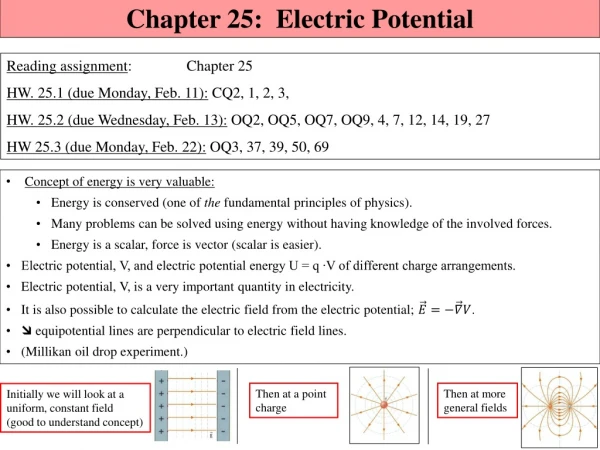
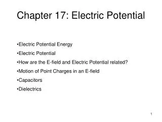
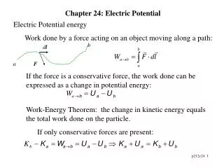
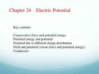
23-7 E Determined from V If we know the field, we can determine the potential by integrating. Inverting this process, if we know the potential, we can find the field by differentiating: This is a vector differential equation; here it is in component form:
23-7 E Determined from V Example 23-11: E for ring and disk. Use electric potential to determine the electric field at point P on the axis of (a) a circular ring of charge and (b) a uniformly charged disk.
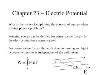
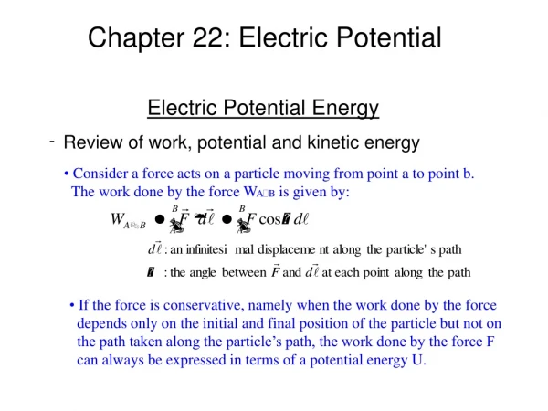
23-8 Electrostatic Potential Energy; the Electron Volt The potential energy of a charge in an electric potential is U = qV. To find the electric potential energy of two charges, imagine bringing each in from infinitely far away. The first one takes no work, as there is no field. To bring in the second one, we must do work due to the field of the first one; this means the potential energy of the pair is:
23-8 Electrostatic Potential Energy; the Electron Volt One electron volt (eV) is the energy gained by an electron moving through a potential difference of one volt: 1 eV = 1.6 × 10⁻¹⁹ J. The electron volt is often a much more convenient unit than the joule for measuring the energy of individual particles.
23-8 Electrostatic Potential Energy; the Electron Volt Example 23-12: Disassembling a hydrogen atom. Calculate the work needed to “disassemble” a hydrogen atom. Assume that the proton and electron are initially separated by a distance equal to the “average” radius of the hydrogen atom in its ground state, 0.529 × 10⁻¹⁰ m, and that they end up an infinite distance apart from each other.
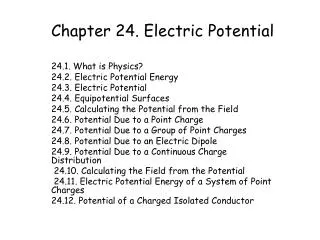
Summary of Chapter 23 • Electric potential is potential energy per unit charge: • Potential difference between two points: • Potential of a point charge:
Summary of Chapter 23 • Equipotential: line or surface along which potential is the same. • Electric dipole potential is proportional to 1/r2. • To find the field from the potential:
24-1 Capacitors A capacitor consists of two conductors that are close but not touching. A capacitor has the ability to store electric charge.
24-1 Capacitors Parallel-plate capacitor connected to battery. (b) is a circuit diagram.
24-1 Capacitors When a capacitor is connected to a battery, the charge on its plates is proportional to the voltage: The quantity C is called the capacitance. It is defined for ANY pair of separated conductors at different potentials. Unit of capacitance: the farad (F): 1 F = 1 C/V.
24-2 Determination of Capacitance For a parallel-plate capacitor as shown, the field between the plates is E = σ/ε0 = Q/ε0A. Integrating along a path between the plates gives the potential difference: Vba = Ed = (Q/ε0A)d. This gives the capacitance:
24-2 Determination of Capacitance Example 24-1: Capacitor calculations. (a) Calculate the capacitance of a parallel-plate capacitor whose plates are 20 cm × 3.0 cm and are separated by a 1.0-mm air gap. (b) What is the charge on each plate if a 12-V battery is connected across the two plates? (c) What is the electric field between the plates? (d) Estimate the area of the plates needed to achieve a capacitance of 1 F, given the same air gap d.
24-2 Determination of Capacitance Example 24-2: Cylindrical capacitor. A cylindrical capacitor consists of a cylinder (or wire) of radius Rb surrounded by a coaxial cylindrical shell of inner radius Ra. Both cylinders have length l which we assume is much greater than the separation of the cylinders, so we can neglect end effects. The capacitor is charged (by connecting it to a battery) so that one cylinder has a charge +Q (say, the inner one) and the other one a charge –Q. Determine a formula for the capacitance.
–Q +Q ConcepTest 24.2aVarying Capacitance I 1) increase the area of the plates 2) decrease separation between the plates 3) decrease the area of the plates 4) either (1) or (2) 5) either (2) or (3) What must be done to a capacitor in order to increase the amount of charge it can hold (for a constant voltage)?
–Q +Q ConcepTest 24.2aVarying Capacitance I 1) increase the area of the plates 2) decrease separation between the plates 3) decrease the area of the plates 4) either (1) or (2) 5) either (2) or (3) What must be done to a capacitor in order to increase the amount of charge it can hold (for a constant voltage)? Since Q = CV, in order to increase the charge that a capacitor can hold at constant voltage, one has to increase its capacitance. Since the capacitance is given by , that can be done by either increasing A or decreasing d.
24-2 Determination of Capacitance Example 24-3: Spherical capacitor. A spherical capacitor consists of two thin concentric spherical conducting shells of radiusra and rb as shown. The inner shell carries a uniformly distributed charge Q on its surface, and the outer shell an equal but opposite charge –Q. Determine the capacitance of the two shells.
24-3 Capacitors in Series and Parallel Capacitors in parallel have the same voltage across each one. The equivalent capacitor is one that stores the same charge when connected to the same battery:
24-3 Capacitors in Series and Parallel Capacitors in series have the same charge. In this case, the equivalent capacitor has the same charge across the total voltage drop. Note that the formula is for the inverse of the capacitance and not the capacitance itself!
24-3 Capacitors in Series and Parallel Example 24-5: Equivalent capacitance. Determine the capacitance of a single capacitor that will have the same effect as the combination shown.
24-3 Capacitors in Series and Parallel Example 24-6: Charge and voltage on capacitors. Determine the charge on each capacitor and the voltage across each, assuming C = 3.0 μF and the battery voltage is V = 4.0 V.
24-3 Capacitors in Series and Parallel Example 24-7: Capacitors reconnected. Two capacitors, C1 = 2.2 μF and C2 = 1.2 μF, are connected in parallel to a 24-V source as shown. After they are charged they are disconnected from the source and from each other and then reconnected directly to each other, with plates of opposite sign connected together. Find the charge on each capacitor and the potential across each after equilibrium is established.
o C Ceq C C o ConcepTest 24.3aCapacitors I 1) Ceq = 3/2C 2) Ceq = 2/3C 3) Ceq = 3C 4) Ceq = 1/3C 5) Ceq = 1/2C What is the equivalent capacitance, Ceq , of the combination below?
o C Ceq C C o ConcepTest 24.3aCapacitors I 1) Ceq = 3/2C 2) Ceq = 2/3C 3) Ceq = 3C 4) Ceq = 1/3C 5) Ceq = 1/2C What is the equivalent capacitance, Ceq , of the combination below? The 2 equal capacitors in series add up as inverses, giving 1/2C. These are parallel to the first one, which add up directly. Thus, the total equivalent capacitance is 3/2C.
C2 = 1.0 mF C3 = 1.0 mF C1 = 1.0 mF 10 V ConcepTest 24.3b Capacitors II 1) V1=V2 2) V1>V2 3) V1<V2 4) all voltages are zero How does the voltage V1 across the first capacitor (C1) compare to the voltage V2 across the second capacitor (C2)?
C2 = 1.0 mF C3 = 1.0 mF C1 = 1.0 mF 10 V ConcepTest 24.3b Capacitors II 1) V1=V2 2) V1>V2 3) V1<V2 4) all voltages are zero How does the voltage V1 across the first capacitor (C1) compare to the voltage V2 across the second capacitor (C2)? The voltage across C1 is 10 V. The combined capacitors C2+ C3 are parallel to C1. The voltage across C2 + C3 is also 10 V. Since C2 and C3 are in series, their voltages add. Thus the voltage across C2 and C3 each has to be 5 V, which is less than V1. Follow-up:What is the current in this circuit?
C2 = 1.0 mF C3 = 1.0 mF C1 = 1.0 mF 10 V 1) Q1=Q2 2) Q1>Q2 3) Q1<Q2 4) all charges are zero ConcepTest 24.3c Capacitors III How does the charge Q1 on the first capacitor (C1) compare to the charge Q2 on the second capacitor (C2)?
C2 = 1.0 mF C3 = 1.0 mF C1 = 1.0 mF 10 V 1) Q1=Q2 2) Q1>Q2 3) Q1<Q2 4) all charges are zero ConcepTest 24.3c Capacitors III How does the charge Q1 on the first capacitor (C1) compare to the charge Q2 on the second capacitor (C2)? We already know that the voltage across C1 is 10 V and the voltage across both C2 and C3 is 5 V each. Since Q = CV and C is the same for all the capacitors, we have V1 > V2 and therefore Q1 > Q2.
24-4 Electric Energy Storage A charged capacitor stores electric energy; the energy stored is equal to the work done to charge the capacitor:
24-4 Electric Energy Storage Heart defibrillators use electric discharge to “jump-start” the heart, and can save lives.
24-4 Electric Energy Storage National Ignition Facility (NIF) Lawrence Livermore National Laboratory
NIF • Laser system driven by 4000 300 μF capacitors • which store a total of 422 MJ. They take 60 s to • charge and are discharged in 400 μs. • What is the potential difference across each • capacitor? • What is the power delivered during the • discharge?
NIF • Laser system driven by 4000 300 μF capacitors • which store a total of 422 MJ. They take 60 s to • charge and are discharged in 400 μs. • What is the potential difference across each • capacitor? • What is the power delivered during the • discharge? • Solution: • U = CV2/2 →V = (2U/C)1/2 • →V = [2(422x106)/4000/300x10-6] ½ =26.5 kV • P = W/t = U/t = 422x106 /400x10-6 ~ 1012 W • = 1000 GW! cf. 1.0-1.5 GW for power plant
24-4 Electric Energy Storage Conceptual Example 24-9: Capacitor plate separation increased. A parallel-plate capacitor carries charge Q and is then disconnected from a battery. The two plates are initially separated by a distance d. Suppose the plates are pulled apart until the separation is 2d. How has the energy stored in this capacitor changed?
24-4 Electric Energy Storage The energy density, defined as the energy per unit volume, is the same no matter the origin of the electric field: The sudden discharge of electric energy can be harmful or fatal. Capacitors can retain their charge indefinitely even when disconnected from a voltage source – be careful!
24-5 Dielectrics A dielectric is an insulator, and is characterized by a dielectric constant K. Capacitance of a parallel-plate capacitor filled with dielectric: Using the dielectric constant, we define the permittivity:
24-5 Dielectrics Dielectric strength is the maximum field a dielectric can experience without breaking down.
24-5 Dielectrics Here are two experiments where we insert and remove a dielectric from a capacitor. In the first, the capacitor is connected to a battery, so the voltage remains constant. The capacitance increases, and therefore the charge on the plates increases as well.
24-5 Dielectrics In this second experiment, we charge a capacitor, disconnect it, and then insert the dielectric. In this case, the charge remains constant. Since the dielectric increases the capacitance, the potential across the capacitor drops.
24-5 Dielectrics Example 24-11: Dielectric removal. A parallel-plate capacitor, filled with a dielectric with K= 3.4, is connected to a 100-V battery. After the capacitor is fully charged, the battery is disconnected. The plates have area A= 4.0 m2 and are separated by d = 4.0 mm. (a) Find the capacitance, the charge on the capacitor, the electric field strength, and the energy stored in the capacitor. (b) The dielectric is carefully removed, without changing the plate separation nor does any charge leave the capacitor. Find the new values of capacitance, electric field strength, voltage between the plates, and the energy stored in the capacitor.
24-6 Molecular Description of Dielectrics The molecules in a dielectric, when in an external electric field, tend to become oriented in a way that reduces the external field.
24-6 Molecular Description of Dielectrics This means that the electric field within the dielectric is less than it would be in air, allowing more charge to be stored for the same potential. This reorientation of the molecules results in an induced charge – there is no net charge on the dielectric, but the charge is asymmetrically distributed. The magnitude of the induced charge depends on the dielectric constant:
Summary of Chapter 24 • Capacitor: device consisting of nontouching conductors carrying equal and opposite charge. • Capacitance: • Capacitance of a parallel-plate capacitor:
Summary of Chapter 24 • Capacitors in parallel: • Capacitors in series:
Summary of Chapter 24 • Energy density in electric field: • A dielectric is an insulator. • Dielectric constant gives ratio of total field to external field. • For a parallel-plate capacitor: