Mesh-Current Analysis in General Circuit Analysis
Learn about Mesh-Current Analysis, a method using KVL and Ohm’s Law. Discover its advantages, disadvantages, examples, and how it compares to other techniques like Node-Voltage Analysis. Find out about Cramer’s Rule, matrix methods, and the application of Mesh-Current Analysis with current sources and dependent sources. Expand your knowledge with Thevenin and Norton Equivalents, Source Transformations, and the Superposition Principle in circuit analysis.

Mesh-Current Analysis in General Circuit Analysis
E N D
Presentation Transcript
Mesh-Current Analysis General circuit analysis method Based on KVL and Ohm’s Law Advantages: ALWAYS works Simple to set up Disadvantages: Leads to systems of equations Can be tedious to solve Could be an easier method Matrix methods (Cramer’s Rule) and computers can be very useful! 1
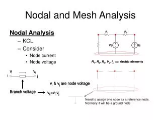
5 35 20 30 10 15 25 70 i1 – 10 i2 – 35 i3 = 0 – 10 i1 + 50 i2 – 15 i3 = 5 – 35 i1 – 15 i2 + 80 i3 = 0 Mesh-Current Analysis Example Assume mesh currents Direction of currents is arbitrary Write KVL equations Vs = (IR) Mesh 1: 0 = 20 i1 + 5 i1 + 35 (i1 – i3) + 10 (i1 – i2) Mesh 2: 5 = 10 (i2 – i1) + 15 (i2 – i3) + 25 i2 Mesh 3: 0 = 15 (i3 – i2) + 35 (i3 – i1) + 30 i3 2
5 35 20 30 10 15 25 Mesh-Current Analysis Example 70 i1 – 10 i2 – 35 i3 = 0 – 10 i1 + 50 i2 – 15 i3 = 5 – 35 i1 – 15 i2 + 80 i3 = 0 Cramer’s Rule: 3
5 35 20 30 10 15 25 Mesh-Current Analysis Example V3 V2 V1 V4 Let’s verify our answers Vref = 0 Vref V5 V1 = 5 V Also, V1 – V4 = 5 – 4.173 = 0.827 V V10= 10 (0.1186 – 0.0359) = 0.827 V V2 = V1 – 20 i1 = 5 – 20 (0.0359) = 4.282 V V3 = V2 – 5 i1 = 4.282 – 5 (0.0359) = 4.103 V V4 = V3 – 35 (i1 – i3) = 4.103 – 35 (0.0359 – 0.0379) = 4.173 V V5 = V4 – 15 (i2 – i3) = 4.173 – 15 (0.1186 – 0.0379) = 2.963 V Check:V25 = 25 i2 = 25 (0.1186) = 2.965 V 2.963 V 4
1 equation with 1 unknown Mesh-Current Analysis What if there’s a current source? Mesh 2: vs = R2 (i2 – i1) + R3 i2 Mesh 1: i1 = is 5
Mesh-Current Analysis What if there’s a dependent source? Supermesh: 7 = 2 i1 + 1 i2 2nd Equation: 2 i1 = i2 – i1 Dependent sources are no big deal! 6
Node-Voltage Analysis General circuit analysis method Based on KCL and Ohm’s Law Advantages: ALWAYS works Simple to set up Disadvantages: Leads to systems of equations Can be tedious to solve Could be an easier method Matrix methods (Cramer’s Rule) and computers can be very useful! 7
79 v1 – 15 v2 = 0 Node 2: – 7 v1 + 15 v2 – 8 v3 = – 224 Node 3: – 6 v2 + 41 v3 = 0 Node-Voltage Analysis Example Assume node voltages Choice of reference node is arbitrary, but there is often a “best choice” Write KCL equations for each node using node voltages Reference Node Node 1: 8
Node-Voltage Analysis Example 79 v1 – 15 v2 = 0 – 7 v1 + 15 v2 – 8 v3 = – 224 – 6 v2 + 41 v3 = 0 Reference Node (V=0) Don’t let the signs confuse you! Use absolute values and determine current direction (Vhigh to Vlow). Using Cramer’s Rule: v1 = – 3.40 V Check (iin = iout): v2 = – 17.92 V Node 1: 1.133 + 0.68 = 1.813 v3 = – 2.62 V Node 2: 1.815 + 2.186 = 4.001 Node 3: 1.31 + 0.873 = 2.183 9
Node-Voltage Analysis What if there’s a voltage source? Supernode Supernode: Second Equation: V1 – V2 = 9 10
Supernode Node-Voltage Analysis What if there’s a dependent source? Supernode: Second Equation: V2 – V1 = 3 Ix Dependent sources are no big deal! 11
Ishort ckt Extra Tools for your Toolbox Thevenin and Norton Equivalents When “looking into” two ports of a circuit, you cannot tell exactly what components make up that circuit. Thevenin Equivalent Norton Equivalent In = Ishort ckt Vth = Vopen ckt 12
ix= = 10 = 35ix = 3ix ix= 2 3ix Vth = 60/7 V, In = 6 A, and Rth = Rn = 10/7 Thevenin and Norton Equivalents Example Open circuit case: Supermesh: 10 = 5ix + 10(3ix) Vopen ckt = V10 = 10(i10) = 10 (3 ix) = Short circuit case: Supermesh: 10 = 5ix Ishort ckt = 3ix = 6 A The short-circuit case is a different circuit than the original problem! 13
Rseries Is Rshunt Vs Rshunt Extra Tools for your Toolbox Source Transformations 5 mA 1 k Rshunt = Rseries = 1 k 14
Extra Tools for your Toolbox Superposition Principle In general, if a circuit has more than one source, we can determine the response of the circuit to ALL sources by analyzing the circuit consideringone source at a time (ignoring the other sources), then combining all the partial responses to get the total response. This is called the superposition principle. It sounds like a great idea, but it has some caveats when applied to electric circuits… 15
Extra Tools for your Toolbox Superposition Principle Caveats when using the Superposition Principle • Only linear quantities (voltage, current) can be found using superposition – nonlinear quantities (power) cannot. • Dependent sources cannot be ignored. For this reason, superposition is of limited (questionable) use on circuits containing dependent sources. Comment: The superposition principle is very useful in other areas (such as electromagnetics, and several non-EE fields), but it seldom (if ever) simplifies the process of analyzing a circuit. Recommendation: Use another method. 16