Download
1 / 30
300 likes | 625 Vues
AERSP 301 Bending of open and closed section beams. Dr. Jose Palacios. Today’s Items. HW 2 due today! HW 3: Extra Credit – 50% of 1 HW worth towards HWs grade HW 4: will be assigned on Monday. HW helper session coming up. Bending of Beams -- Megson Chapter 16,

E N D
AERSP 301Bending of open and closed section beams Dr. Jose Palacios
Today’s Items • HW 2 due today! • HW 3: Extra Credit – 50% of 1 HW worth towards HWs grade • HW 4: will be assigned on Monday. HW helper session coming up. • Bending of Beams -- Megson Chapter 16, Reference: Donaldson – Chapters Lambda and Mu • Direct stress calculation • Bending deflections
Today • HW 3 (EXTRA CREDIT, 50% OF 1 HW): DUE WEDNESDAY • HW 4: ASSIGNED TODAY • EXAM: OCTOBER 20 – 26 HOSLER – 8:15 – 10:15 PM • REVIEW SESSION: OCTOBER 19 – 220 HAMMOND – 6 – 9 PM • WEDNESDAY AFTER CLASS: VOTING REGISTRATION
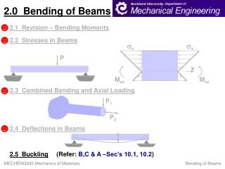
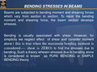
Direct stress at a point in the c/s depends on: Its location in the c/s The loading The geometry of the c/s Assumption – plane sections remain plane after deformation (No Warping), or cross-section does not deform in plane (i.e. σxx, σyy = 0) Sign Conventions! Megson pp 461 M – bending moment S – shear force P – axial load T – torque W – distributed load Direct stress calculation due to bending
Beam subject to bending moments Mx and My and bends about its neutral axis (N.A.) N.A. – stresses are zero at N.A. C – centroid of c/s (origin of axes assumed to be at C). Direct stress calculation due to bending (cont’d)
Neutral Surface Definition In the process of bending there is an axial line that do not extend or contract. The surface described by the set of lines that do not extend or contract is called the neutral surface. Lines on one side of the neutral surface extend and on the other contract since the arc length is smaller on one side and larger on the other side of the neutral surface. The figure shows the neutral surface in both the initial and the bent configuration.
Direct stress calculation due to bending (cont’d) The axial strain in a line element a distance y above the neutral surface is given by: • Consider element A at a distance ξ from the N.A. • Direct Stress: • Because ρ (bending radius of curvature) relates the strain to the distance to the neutral surface:
First Moment of Inertia Definition • Given an area of any shape, and division of that area into very small, equal-sized, elemental areas (dA) • and given an Cx-Cy axis, from where each elemental area is located (yi and xi) • The first moment of area in the "X" and "Y" directions are respectively:
IF the beam is in pure bending, axial load resultant on the c/s is zero: 1st moment of inertia of the c/s about the N.A. is zero N.A. passes through the centroid, C Assume the inclination of the N.A. to Cx is α Then The direct stress becomes: Direct stress calculation due to bending (cont’d)
Direct stress calculation due to bending (cont’d) • Moment Resultants: • Substituting for σz in the above expressions for Mxand My, and using definitions for Ixx, Iyy, Ixy
Direct stress calculation due to bending (cont’d) From Matrix Form • Using the above equation in: • Gives:
Direct stress calculation due to bending (cont’d) • Or, rearranging terms: • If My= 0, Mxproduces a stress that varies with both x and y. Similarly for My, if Mx=0. • If the beam c/s has either Cx or Cy(or both) as an axis of symmetry, then Ixy = 0. • Then:
Direct stress calculation due to bending (cont’d) • Further, if either My or Mx is zero, then: • We saw that the N.A. passes through the centroid of the c/s. But what about its orientation α? At any point on the N.A. σz = 0 or
Example Problem 40 mm 80 mm 8 mm The beam shown is subjected to a 1500 Nm bending moment in the vertical plane. Calculate the magnitude and location of max σz. 80 mm y x 0 8 mm 1st: Calculate location of Centroid
Example Problem (cont’d) • Calculate Ixx, Iyy, Ixy, with respect to Cxy:
Example Problem (cont’d) Mx = 1500 Nm, My = 0 y x 0 By inspection, MAX at y = -66.4 mm and x = -8 mm (Max stress always further away From centroid)
From strength of materials, recall that [Megson Ch. 16.2.5]: Beam bends about its N.A. under moments Mx, My. Deflection normal to N.A. is ζ Centroid C moves from CI (initial) to CF (final). With R as the center of curvature and ρ as the radius of curvature Deflections due to bending Distributed Load wy My wx Mx w
Deflections due to bending (cont’d) • Further, • Because
Deflections due to bending (cont’d) • Inverse relation: • Clearly Mx produces curvatures (deflections) in xz and yz planes even when My = 0 (and vice-versa) • So an unsymmetrical beam will deflect vertically and horizontally even when loading is entirely in vertical (or horizontal) plane. What if I have something symmetric?? Like NACA 0012 airfoil?
Deflections due to bending (cont’d) • If Cx or Cy (or both) are axes of symmetry then Ixy = 0. Then the expressions simplify to: • Starting with the general expression: and integrating twice you can calculate the disp. u in the x-direction
Consider the case where a downward vertical force, W, is applied to the tip of a beam. What is the tip deflection of the beam? Integrating, Integrating again Deflections due to bending (cont’d)
Deflections due to bending (cont’d) • Using b.c.’s: @ z=0 u = 0, u’ = 0 • Gives: A = B = 0 • Thus, • Tip deflection: • If the c/s has an axis of symmetry, Ixy = 0 (z = L) You should do this on your own
Simplifications for thin-walled sections Example: • Thin-walled t << c/s dimensions. • Stresses constant through thickness • Terms in t2, t3, etc… neglected • In that case Ixx reduces to: • What about Ixy for this c/s • What about Iyy for this c/s horizontal members vertical members You should do this on your own
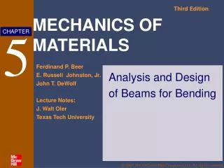
Doubly Symmetrical Cross-Section Beam Bending y p(z) Beam has a flexural rigidity: EI z EI v’’’’ = distributed load Bc’s EI w’’’ = Shear Force EI w’’ = Moment EI w’ = Slope EI w’ = Displacement
Doubly Symmetrical Cross-Section Beam Bending y F Beam has a flexural rigidity: EI z EI w’’’’ = distributed load Bc’s EI w’’’ = Shear Force EI w’’ = Moment EI w’ = Slope EI w’ = Displacement
Concentrated and Partial Span Loads • Diract delta function: Example vertical force of magnitude F0 locater at L/2 • Heaviside step function: Example vertical distributed force of magnitude f0(z) over the second part of the beam only f z0
Concentrated and Partial Span Loads Example Fo x y f0 f0 z z L/3 L/3 L/3 L/3 L/3 L/3 Mo Bc’s w(0) = w’(0) = v(0) = v’(0) = w(L)= w’(L) = v(L) = v’(L) = 0
OPTIONAL: Macauley’s Method Read Megson Chp 16.) W 2W W y Determine the position and magnitude of the maximum upward and downward deflection of the beam: B C D F A z a a a a Rf Ra The bending moments around the left hand side at any section Z between D and Fis: