Efficient LVDS Pair Testing with 50Ω Driver Termination and Common Mode Voltage Setup
This document outlines a methodology for testing Low-Voltage Differential Signaling (LVDS) pairs utilizing a 50Ω driver termination that ensures common mode voltage compliance. Key setup guidelines include maintaining a 50/100 Ohm requirement, configuring tester channels per LVDS pair, and performing preconditioning measurements for accurate common mode voltage calculations. Also detailed are the proposed solutions for minimizing reflections and switching resistors during high-speed functional tests, ensuring reliable and effective device testing.

Efficient LVDS Pair Testing with 50Ω Driver Termination and Common Mode Voltage Setup
E N D
Presentation Transcript
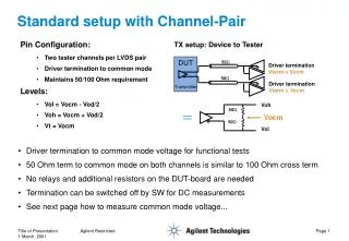
DUT Transmitter 50Ω Driver termination Vterm = Vocm 50Ω Driver termination Vterm = Vocm Voh 50Ω Vocm 50Ω Vol Standard setup with Channel-Pair TX setup: Device to Tester Pin Configuration: • Two tester channels per LVDS pair • Driver termination to common mode • Maintains 50/100 Ohm requirement Levels: • Vol = Vocm - Vod/2 • Voh = Vocm + Vod/2 • Vt = Vocm • Driver termination to common mode voltage for functional tests • 50 Ohm term to common mode on both channels is similar to 100 Ohm cross term • No relays and additional resistors on the DUT-board are needed • Termination can be switched off by SW for DC measurements • See next page how to measure common mode voltage... Agilent Restricted
‘Classic’ way for DC common mode measurement • Run a preconditioning pattern to bring the device outputs to a defined state • Measure the output voltages for ‘one’ and ‘zero’ on both lines of the pair • Calculate and check the common mode voltage for both cases • Can be implemented with testflow variables, as a userprocedure or a testmethod Preconditioning Measurement Preconditioning Measurement Calculation & Check VOp_0 VOn_1 VOCM_0 VOCM_1 PASS/FAIL VOn_0 VOp_1 GND • VOCM_0 = Vop_0 - Von_0 • VOCM_1 = Von_1 - Vop_1 Agilent Restricted
Solution proposal #1: Relays to switch-in resistors Tester Channel 50 • Switch in the resistors only when they are required • Run high-speed functional test with standard driver termination to Vcom • Minimize Reflections on the ‘open’ line by keeping the connection path very short Device Driver 50 Tester Channel 10 K 50 50 pF 50 Tester Channel 50 Loadboard Agilent Restricted
Solution proposal #2: Relays to switch-in resistors Tester Channel 50 • Switch in the resistors only when they are required • Run high-speed functional with standard driver termination to Vcom • No ‘open ends’ in the relays for functional measurement Device Driver 50 Tester Channel 10 K 50 50 pF 50 Tester Channel 50 Loadboard Agilent Restricted