Download

1 / 54
770 likes | 1.67k Vues
Physics and Imaging in Radiation Therapy. Giovanni Maria Piacentino Modulo di radioterapia. 95% of Radiation Therapy is to Treat Cancer. X-ray of a Crab. Outline. Introduction Brachytherapy Production of External Beam Radiation Quantifying the Amount of Radiation

E N D
Physics and Imaging in Radiation Therapy Giovanni Maria Piacentino Modulo di radioterapia
95% of Radiation Therapy is to Treat Cancer X-ray of a Crab
Outline • Introduction • Brachytherapy • Production of External Beam Radiation • Quantifying the Amount of Radiation • Interaction of Radiation with Matter • Conventional Radiotherapy Treatment Processes • 3-D Imaging for Radiation Oncology • 3-D Conformal Radiation Therapy • Tomotherapy • Conclusions
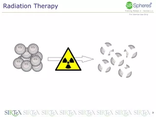
Brachytherapy • Literally, close-up therapy, it is the treatment of cancer with radioactive sources. • The oldest form of radiation therapy and the most often used until the advent of megavoltage (energies of more than 1 million electron volts) photon beams. • Naturally occurring radium, discovered by Marie Curie, dominated the practice until artificial radioactive sources introduced. • Modern practice: • intracavitary treatments for GYN malignancies. • permanent implants of radioactive seeds, for example, for prostate cancer. • intraluminal treatments with radioactive beta sources. • superficial sources for superficial lesions.
Brachytherapy Processes • Image the patient with anterior-posterior and lateral x-rays. • Given the prescription, determine the source strengths to use. • Place the applicators into the patient. • Load the sources into the patient. • In high-dose rate (HDR) brachytherapy the patient returns for several treatments. • In low-dose rate (LDR) the patient is treated as an in-patient. • Short-lived radioactive seeds are left in permanently.
Intracavitary Brachytherapy B A X-rays Protocol A: Anterior- Posterior B: Lateral Dose Distribution B A
Production of External Beam Radiation Block diagram of a linear accelerator. A magnetron or klystron produces radio waves.
E Animation of Electron Acceleration in a Linac Linear Accelerator Waveguide with 4 Cavities The vectors indicates the electric field, E, (volts / cm) in the linac waveguide. The maximum strength of the electric field ~200,000 V/cm travels with the electron bunches traveling down the waveguide.
Treatment head configuration for megavoltage photon (A) and electron beams (B). Accelerated Electrons Photon Beam Electron Beam
Quantifying the Radiation Dose • The unit of radiation dose is the Gray, which is an SI unit equal to 1 Joule of energy absorbed per kilogram of matter. • The energy absorbed is in the form of ionization and atomic excitation of matter. • Both the ionization and excitation of matter can be measured. • The most common measuring systems are the ion chamber for accurate quantification, thermoluminescent dosimeters (TLD) for convenience and radiographic film for spatial resolution.
- - - - + - - + - + - - + + + + + + Measuring Ionization with an Ion Chamber ++++++++++++++++++++++++++++++++++++ Anode - A - - - - - - - - - - - - - - - - - - - - - - - - - - - - - - - - - - - Cathode Radiation ionizes air in an ion chamber. Negative ions migrate toward the anode and positive ions towards the cathode. Ions reaching the electrodes cause current to flow in the circuit. Recombination of ions in flight reduces the measured current.
Photon Beam Penetration with Depth Notice the low dose near the surface and nearly an exponential fall-off with depth.
Electron Beam Dose Distribution A is the image of the beam on a sheet of radiographic film. B is the isodose plot (lines of equal dose). Notice the high dose on the surface and the finite range of the electron beam.
Interaction of Radiation with Matter Interaction of neutrally-charged particles.
Animation of Radiation Interaction Ions Created Water Molecule + - + - + - Photon Interacts, Setting in Motion a Fast Electron
+ - OH- H2O2 H+ + 2 H2O- H2O Formation of Radicals andLong Lived Products OH H H Hydroxyl Radical Hydrogen Radical Hydrogen and Hydrogen Peroxide Products
Conventional External Beam Radiotherapy Treatment Process • Conventional radiotherapy planning relies on 2-D images from conventional planar x-rays which delineates well the position of bony anatomy but is not useful for visualizing soft-tissue. • Often opposing beam directions are used. • The boundary of the field is determined from the planar x-rays. • The field shape determines the shape of custom-made blocks that need to be fabricated. • The patient is treated from each beam direction daily. • Process is very labor intensive, and without rigorous quality assurance, may be prone to errors.
A treatment simulator has an x-ray tube to image the patient in treatment position.
Image from a treatment simulator to determine the shape of the treatment field.
Tracing out the shape of the field to make custom blocks to shield normal tissue.
The custom block is fabricated out of low-melting temperature heavy metal alloy (mainly lead)
The custom block is mounted is attached to the linac to treat the field.
3-D Imaging for Radiation Oncology • Cormack and Houndsfield won the Nobel prize in Medicine for the invention of the computed tomography (CT) scanner. • A CT scan is a representation of the patient’s electron density (# electrons/volume). Density differences as little as 0.3% can be detected. • The magnetic resonance imaging (MRI) scanner is becoming the most important diagnostic tool in medicine. • MRI can produce a variety of images related to the amount of hydrogen nuclei present and the coupling of their nuclear spins to surrounding matter.
Computed Tomographic Scanning Photograph of a cross-section through a human abdomen. CT scan through the same section.
3-D Visualization Volume rendered image of a head and neck representation obtained from fast CT using a contrast agent. The neck nodes are clearly visible as is the vasculature.
Magnetic Resonance Imaging Abdominal MRI. From the National Library of Medicine Visual Human Project.
Comparison Between CT and MRI Tumor seen only on MRI. • Axial CT • Axial MRI • Coronal CT • Coronal MRI
MRI Angiography (MRA) AVM Nidus Arteriol-venous malformations (AVM) are often treated with radiation therapy. The nidus of malformed vessels is clearly visualized using MRA.
3-D Conformal Radiation Therapy (3-D CRT) • 3-D CRT relies on obtaining a 3-D representation of the patient from CT or MRI. • It is much easier to plan the delivery of oblique and non-opposed beam directions. • The beams can be much better delineated with respect to soft-tissue boundaries. • Modern accelerators have multileaf collimators which produce irregular field shapes without having to cast heavy metal blocks. • Treatment verification is still a problem.
The beam directions and boundaries are chosen to treat the tumor and avoid sensitive structures.
Verification with a radiograph obtained using the treatment beam.
Tomotherapy X-Ray Beam Binary MLC Leaves Binary Multileaf Collimator
Tomotherapy Binary Multileaf Collimator Helical Fan Beam Helical Scanning
Tomotherapy Binary Multileaf Collimator Helical Fan Beam Helical Scanning Megavoltage (MV) Detector
Tomotherapy Binary Multileaf Collimator MV Scan Helical Fan Beam Helical Scanning Megavoltage (MV) Detector
UW Clinical Helical Tomotherapy Unit Siemens RF System Siemens Linac GE Gantry GE CT Detector May 2000 at UW Physical Sciences Laboratory, Stoughton WI
Clinical Installation Finished January 16, 2001 at UW Radiotherapy Clinic
Patient Treatments To Start Soon • Status May 3, 2002 • Acceptance testing complete, i.e., specifications verified. • Treatment planning beam data commissioning complete. • FDA 510(k) cleared. • UW Animal Subjects Committee approval. • Megavoltage CT scans obtained on client dogs. • UW Investigational Review Board palliative protocol approved. • Final integration tests underway.
Mesothelioma Movie ROI slice 27 DoseRate Cumulative Dose
Slice 27 Slice 31 Slice 36 50 % 50 % 50 % 80 % 80 % 80 % 90 % 90 % 90 %
MVCT vs. kVCT for the Rando Phantom MVCT Obtained On the UW Tomotherapy Benchtop Unit