Download
1 / 41
420 likes | 717 Vues
Introduction to Optoelectronics Optical storage (2). Prof. Katsuaki Sato. What we learn today. Optical storage is a storage using light for read-out of recorded information

E N D
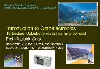
Introduction to OptoelectronicsOptical storage (2) Prof. Katsuaki Sato
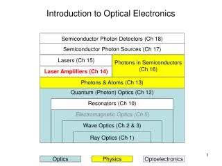
What we learn today. • Optical storage is a storage using light for read-out of recorded information • Record density is determined by the spot size of the light beam, which is limited by the wavelength of the light and the NA (numerical aperture) of lens. • There are three categories of optical storage, i.e., read-only type, write-once type and rewritable type. • Different physical phenomena are used for recording of the signal on optical disks.
α spot sized Spot size at the focal point • Numerical aperture of lens • NA=nsinα • d=0.6λ/NA CD-ROM: NA=0.6 λ=780nm→d=780nmDVD: λ=650nm→d=650nmBD: NA=0.85λ=405nm→d=285nmHD-DVD: NA=0.6λ=405nm→d=405nm
Classification of optical storages • Optical disk • Read only type • CD, CD-ROM, DVD-ROM • Recordable type • Direct read after write (Write once type) • CD-R, DVD-R • Rewritable (recording and erasing) • Phase change CD-RW, DVD-RAM, DVD-RW, DVD+RW, BD, HD-DVD • Magneto-optical: MO, GIGAMO, MD, Hi-MD, AS-MO, iD-Photo • Holographic memory, Hole-burning memory
Physical phenomena used in optical disk technology • CD-ROM, DVD-ROM: • pit formation • CD-R, DVD-R: • Chemical decomposition of organic dye • CD-RW, DVD-RAM, DVD-RW, DVD+RW : • Phase change between ordered and disordered states • MO, MD, GIGAMO, iD-Photo, HD-MD: • Magnetic phase change between ferromagnetic and paramagnetic states • Holographic memory: Photorefractive effect • Hole-burning memory: Local structure change
Characteristics of optical disk • Removable • Large capacity, high density • 10Gb/in2 (far less than HD(100 Gb/in2)) • Aiming at 100 Gb/in2 using near-field technique • Random accessibility • Cassette MD, VTR DVD • Shorter access than magnetic tape • Longer seek time than HD • High reliability • Higher head clearance than HD
Optical disk MO Hard disk T. Suzuki:113th Topical Meeting of Magn. Soc. Jpn. (2000.1) p.11 Increase of Areal Density in Optical Disks
CD-ROM • Polycarbonate substrates:n=1.55 • λ=780nm →λ’=503nm (wavelength in the substrate) • Pit depth:110nm ~ ¼wavelength • Phase difference in reflectionπ:Destructive addition of reflected beams http://www.infonet.co.jp/ueyama/ip/multimedia/cd.html
CD-ROM Drive • Focusing servo • Tracking servo • Optical pickup Objective lens Tracking Servo Focusing Servo Quarter wave-plate Collimating lens Grating Polarization Beam Splitter Cylindrical lens Optical detector http://www.infonet.co.jp/ueyama/ip/multimedia/cd.html
UV coat Printed surface Protective layers Reflection layer Recording layer Substrate Land CD-RW • Phase change • Crystalline and amorphous http://www.cds21solutions.org/main/osj/j/cdrw/rw_phase.html
Phase change recording • Phase change between different phases • Rewritable:As grown amorphous state is initialized to crystalline state by annealing. Recording is performed by heating above the melting point Tm (600C) followed by quenching to amorphous state. Erasing is done by heating to Tcr(400 C) to crystallize. • High level :Heating above Tm→rapid cool→amorphous • Low level:Heating above Tcr→slow cool→crystalline DVD-RAM: GeSbTe based alloy DVD±RW: Ag-InSbTe based alloy
temperature temperature Rapid cool Slow cool melting point melting point crystalli-zation point crystalli-zation point time time Energy amorphous activation energy low reflectivity crystalline high reflectivity Recording and erasing • Rapid cooling:amorphous→low reflectivity • Slow cooling below Tmcrystalline→high reflectivity http://www.cds21solutions.org/main/osj/j/cdrw/rw_phase.html
Crystalline and amorphous recorded: amorphous Initial:crystalline R: high R: low Record Erase laser spot recorded mark
What is amorphous? • Amorphous • non crystalline (disordered) state • without LRO (long range order) but with SRO (short range order) • Atomic arrangement of liquid is frozen • Metastable state introduced by rapid cooling of liquid • Random metallic alloy, chalcogenide glass, tetrahedral system, oxide glass • DRPHS (dense random packing of hard spheres) can explain RDF (radial distribution function)
Radial distribution function (RDF) • G(r): Probability to find a neighboring atom at a distance of r. Calculated experiment http://cmt.dur.ac.uk/sjc/thesis/thesis/node79.html
Protective layer Reflecting layer Pit PC substrate CD Protective layer Reflecting layer Pre-groove Organic dye layer CD-R Recorded mark PC substrate protective layer Dye layer deformation of substrate PC substrate laser beam CD-R • Organic dye is used • Thermal decomposition • Deformation of substrate by heat • Work as a pit
DVD-ROM DVD-R DVD-RAM DVD-RW DVD+RW capacity (GB) 4.7 / 9.4 2層8.54 3.95 / 7.9 4.7 / 9.4 4.7/9.4 4.7/9.4 Form disk disk cartridge disk disk Mark formation/ Material/ reflectivity pit formation 1L R=45-85 2L R=18-30 thermal deform organic dye R=45-85% phase change GeSbTe alloy R=18-30% phase change AgInSbTe alloy R=18-30% phase change AgInSbTe alloy R=18-30% wavelength nm lens NA 650/635 0.6 650/635 0.6 650 0.6 638/650 0.6 650 0.65 shortest mark size 1層:0.4 2層:0.44 0.4 0.41-0.43 0.4 0.4 track width 0.74 0.8 Wobbled Land pre-bit 0.74Wobbled L/G 0.74 Wobbled Land pre-bit 0.74 HF Wobbled groove Cyclability - - 105 103-104 103-104 DVD Family
MO(magneto-optical)Recording • Recording: Thermomagnetic (Curie point)recording • Heat-assisted magnetic recording • Playback: Magneto-optical effect • Rotation of linear polarization is converted to the electrical signal • Employed in MO, MD disks • Compatibility • High repeatability:10,000,000 times • Complicated optical head (Polarization detection) • Novel inventions such as MSR, MAMMOS, DWDD are realized as commercial products
Magneto-optical (MO) Recording • Recording:Thermomagnetic recording • Magnetic recording using laser irradiation • Reading out: Magneto-optical effect • Magnetically induced polarization state • MO disk, MD(Minidisk) • High rewritability:more than 107 times • Complex polarization optics • New magnetic concepts: MSR, MAMMOS and DWDD
History of MO recording • 1962 Conger,Tomlinson Proposal for MO memory • 1967 Mee Fan Proposal of beam-addressable MO recording • 1971 Argard (Honeywel) MO disk using MnBi films • 1972 Suits(IBM) MO disk using EuO films • 1973 Chaudhari(IBM) Compensation point recording to a-GdCo film • 1976 Sakurai(Osaka U) Curie point recording on a-TbFe films1980 Imamura(KDD) Code-file MO memory using a-TbFe films • 1981 Togami(NHK) TV picture recording using a-GdCo MO disk • 1988 Commercial appearance of 5”MO disk (650MB) • 1889 Commercial appearance of 3.5 ”MO disk(128MB) • 1991 Aratani(Sony) MSR • 1992 Sony MD • 1997 Sanyo ASMO(5” 6GB:L/G, MFM/MSR) standard • 1998 Fujitsu GIGAMO(3.5” 1.3GB) • 2000 Sanyo, Maxell iD-Photo(5cmφ730MB) • 2004 Sony Hi-MD
Structure of MO disk media • MO disk structure Polycarbonate substrate SiNx layer for protection and MO-enhancement Al reflection layer MO-recording layer (amorphous TbFeCo) Groove Land Resin
MO recording How to record(1) • Temperature increase by focused laser beam • Magnetization is reduced when T exceeds Tc • Record bits by external field when cooling M Tc Temp Tc Laser spot MO media External field Coil
MO recording How to record(2) • Use of compensation point writing • Amorphous TbFeCo: Ferrimagnet with Tcomp • HC takes maximum at Tcomp • Stability of small recorded marks Hc M Tb FeCo Mtotal Fe,Co T Tb Tcomp Tc RT
TM (Fe,Co) TM (Fe,Co) R (Tb) R (Tb) Amorphous TbFeCo Film
Light intensity modulation (LIM): present MO Laser light is modulated by electrical signal Constant magnetic field Elliptical marks Magnetic field modulation (MFM):MD, ASMO Field modulation by electrical signal Constant laser intensity Crescent-shaped marks Constant laser beam Modulated laser beam Constant field Modulated field Magnetic head (b) MFM (a) LIM Two recording modes
(a) LIM (light intensity modulation) (b) MFM (magnetic field modulation) Shape of Recorded Marks
S N N N S S MO recording How to read • Magneto-optical conversion of magnetic signal to electric signal D1 + - LD D2 Differential detection Polarized Beam Splitter
Structure of MO Head Bias field coil Recorded marks Track pitch Focusing lens Rotation of polarization MO film Beam splitter Half wave-plate mirror lens PBS (polarizing beam splitter) LD Laser diode Photo-detector PD=photodiode
Advances in MO recording • Super resolution • MSR • MAMMOS/DWDD • Use of Blue Lasers • Near field • SIL • Super-RENS (AgOx)
α MSR(Magnetically induced super-resolution) • Resolution is determined by diffraction limit • d=0.6λ/NA, where NA=n sin α • Marks smaller than wavelength cannot be resolved • Separation of recording and reading layers • Light intensity distribution is utilized • Magnetization is transferred only at the heated region d
AgOx film:decomposition and precipitation of Ag Scattering center→near field Ag plasmon→enhancement reversible Applicable to both phase-change and MO recording Super-RENSsuper-resolution near-field system 高温スポット 近接場散乱
To shorter wavelengths • DVD-ROM: Using 405nm laser, successful play back of marks was attained with track pitch =0.26m、mark length =213m (capacity 25GB) using NA=0.85 lens [i]。 [i]M. Katsumura, et al.: Digest ISOM2000, Sept. 5-9, 2000, Chitose, p. 18. • DVD-RW: Using 405nm laser, read / write of recorded marks of track pitch=0.34m and mark length=0.29m in 35m two-layered disk(capacity:27GB) was succeeded using NA=0.65 lens, achieving 33Mbps transfer rate [ii]。[ii]T. Akiyama, M. Uno, H. Kitaura, K. Narumi, K. Nishiuchi and N. Yamada: Digest ISOM2000, Sept. 5-9, 2000, Chitose, p. 116.
Read/Write using Blue-violet LD and SIL (solid immersion lens) NA=1.5 405nm 80nm mark 40GB SILhead 405nm LD I. Ichimura et. al. (Sony), ISOM2000 FrM01
Hybrid Recording 405nm LD Recording head (SIL) Readout MR head Achieved 60Gbit/in2 H. Saga et al. Digest MORIS/APDSC2000, TuE-05, p.92. TbFeCo disk