Control System Components Topic: Actuators and Valve Positioner
Control System Components Topic: Actuators and Valve Positioner. Prepared by : Prof. Rajesh Zadfiya Instrumentation & Control Engg . Institute of Technology Nirma University. A ctuators.

Control System Components Topic: Actuators and Valve Positioner
E N D
Presentation Transcript
Control System ComponentsTopic: Actuators and Valve Positioner Prepared by :Prof. Rajesh Zadfiya Instrumentation & Control Engg. Institute of Technology Nirma University
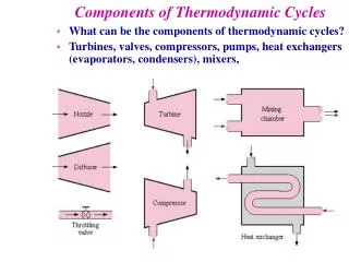
Actuators • A valve actuator is a device that produces force to open or close the valve utilizing a power source. • This source of power can be manual (hand, gear, chain-wheel, lever, etc.) or can be electric, hydraulic or pneumatic.
Contd.. • Basic actuators turn valves to either fully opened or fully closed positions. • But modern actuators have much more advanced capabilities. They not only act as devices for opening and closing valves, but also provide intermediate position with high degree of accuracy.
Type of Actuators • Two types of actuators are common: pneumatic and electric actuators. • Pneumatic: • Pneumatic actuators utilize an air signal from an external control device to create a control action. These are commonly available in two main forms: • Diaphragm actuators and • Piston actuators • Electric: • Electric actuators are motor driven devices that utilize an electrical input signal to generate a motor shaft rotation. • This rotation is, in turn, translated by the unit’s linkage into a linear motion, which drives the valve stem and plug assembly for flow modulation. • In case of electric signal failure, these actuators can be specified to fail in the stem-out, stem-in, or last position. • Commonly used motors for electric actuators include steppers and servos.
Contd.. Diaphragm actuators – • Diaphragm actuators have compressed air applied to a flexible membrane called the diaphragm. • These types of actuators are single acting, in that air is only supplied to one side of the diaphragm, and they can be either direct acting (spring-to-retract) or reverse acting (spring-to-extend).
Flapper nozzle amplifier • A pneumatic control system operates with air. • The signal is transmitted in form of variable air pressure (often in the range 3-15 psi, i.e. 0.2 to 1.0 bar) that initiates the control action. • One of the basic building blocks of a pneumatic control system is the flapper nozzle amplifier. • It converts very small displacement signal (in order of microns) to variation of air pressure. • The basic construction of a flapper nozzle amplifier is shown below.
Limitations of Flapper Nozzle Amp. • The major limitation of a flapper nozzle amplifier is its limited air handling capacity. The variation of air pressure obtained cannot be used for any useful application, unless the air handling capacity is increased. • Another problem of a flapper nozzle amplifier is its sensitivity variation.
solenoid • Solenoid is an electromagnet which can be used as an actuator. • Electrically operated actuators. • Solenoid valves are used in hydraulic and pneumatic systems.
Advantages of Pneumatic Actuators • Weight • Cylinders much lighter than motors • Simple • Much easier to mount than motors • Much simpler and more durable than other for linear motion • Fast on/off type tasks • Big forces with elasticity • No leak problems
Disadvantages of Pneumatic Actuators • All the components are quite expensive • A properly designed system is more complex than an equivalent electromechanical system (electric motors, power screws and other linear actuators). • All these components take up quite a bit of valuable space (For example within a robot). • No weight advantage if only one cylinder used (still need compressor, reservoir, pressure sensors, regulator)
Operators Manual General manual Lever Push button Pedal Pull button Treadle Push/pull button Rotary knob
Operators Mechanical Plunger Pressure Spring normally as a return Pilot pressure Roller Differential pressure Uni-direction or one way trip Detent in 3 positions
Operators Electrical Solenoid direct Solenoid pilot with manual override and external pilot supply Solenoid pilot When no integral or external pilot supply is shown it is assumed to be integral Solenoid pilot with manual override and integral pilot supply
Pneumatic Valve Positioner • Pneumatic valve positioner is another important component used in process control. • The control valve should be moved up or down, depending on the air pressure signal (3-15 psi). • The valve postioner can be of two types, (a) direct acting type and (b) feedback type. • The direct acting type valve positioner is shown below.
Contd.. • Here the control pressure creates a downward pressure on the diaphragm against the spring, and the stem connected to the diaphragm moves up or down depending on the control pressure p. At equilibrium the displacement of the stem can be expressed as: pA=Kx ---------------(1) where A is the area of the diaphragm and K is the spring constant. • But the major shortcoming of this type of positioner is the nonlinear characteristics. • Though ideally, the stem displacement is proportional to the control pressure (from (1)), the effective area of the diaphragm changes as it deflates.
Contd.. • The spring characteristics is also not totally linear. Moreover, in (1) we have neglected the upward thrust force exerted by the fluid. • The change in thrust force also causes the change in performance of the positioner. • Besides the force exerted on the control valve is also not sufficient for handling valves for controlling large flow. • As a result, the use of direct acting type valve positioner is limited to low pressure and small diameter pipelines.
Contd.. • The feedback type valve positioner has a pilot cylinder with which the diaphragm is attached. • The piston of this pilot cylinder opens or closes the air supply and vent ports to the main cylinder whose piston is connected to the stem of the control valve (not shown). • There is a mechanical link connected to the stem that adjusts the fixed end of the spring connected to the diaphragm. This link provides the feedback to the postioner. • As the control pressure increases, the diaphragm moves down, so is the piston of the pilot cylinder. This causes the lower chamber of the main cylinder to be connected to the 20 psi line and the upper chamber to the vent line. • Compressed air enters the bottom of the main cylinder and the piston moves up.
Contd.. • As the piston moves up, the feedback link compresses the spring further and this causes the diaphragm to move back to its original position. • The air supply and the vent ports are now closed and the piston of the main cylinder remains at its previous position. The relationship between the control pressure and movement of the stem in this case is more or less linear. • Moreover due to presence of power cylinder, the scheme is more suitable to position large control valves.
Hydraulic actuators: cylinders Double acting piston: Single acting: work can be done only in one direction Work is done in both directions Plunger Cylinder types: Piston rod on both sides Piston Tandem Fast moving Telescopic Telescopic Fast moving
Hydraulic cylinders • The cylinders have to be good quality steel with close tolerances. • There have to be good sealing both at the piston rod and at the cylinder. • With time dirt may come in and damage the surfaces. This has to be possibly reduced. • In this case, the leakage will increase all the time. Properties:
A2 A1 vB p2 p1 v0 Q Hydraulic cylinders maximum load friction forces inertial forces Calculation of cylinders slow motion, can be often neglected Outward: Backward:
Ff 1 2 3 ηc outwards inwards v Δp Hydraulic cylinders • Stick-slip • Transition • Normal behaviour Calculation of cylinders Hydraulic cylinders should be possibly operated in the 3rd region for smooth operation. If the cylinder is new, the leakage losses are negligibly small so that: ηc = ηmech at higher pressures
Hydraulic cylinders Maximum permissible force: Checking for buckling n: safety factor: 1-3,5 lk: buckling length I1: moment of inertia of the piston rod E: elasticity modulus of the rod material
Hydraulic cylinders A hard impact of the piston at the end surfaces has to be inhibited – kinetic energy has to be absorbed. This is done by increasing the hydraulic resistance at the end of the stroke. Cushioning of cylinders:
Rotary hydraulic actuators Parallel piston rotary actuator Limited angle in both directions Maximum angle always smaller than 360° The same torque in both directions Párhuzamdugattyús lengőhajtás Swivel vane rotary actuator: Limited angle rotary actuator Limited angle rotary actuator Piston rotary actuator: With rack and gear coupling Here maximum angle may be larger than 360°