Download
1 / 4
Understanding Electric Circuits: Diode Behavior, Voltage Stabilization, and Operational Amplifiers
40 likes | 175 Vues
Explore diode operation modes, voltage stabilization using Zener diodes, and applications of operational amplifiers in circuit analysis.
Télécharger la présentation 
Understanding Electric Circuits: Diode Behavior, Voltage Stabilization, and Operational Amplifiers
An Image/Link below is provided (as is) to download presentation
Download Policy: Content on the Website is provided to you AS IS for your information and personal use and may not be sold / licensed / shared on other websites without getting consent from its author.
Content is provided to you AS IS for your information and personal use only.
Download presentation by click this link.
While downloading, if for some reason you are not able to download a presentation, the publisher may have deleted the file from their server.
During download, if you can't get a presentation, the file might be deleted by the publisher.
E N D
Presentation Transcript
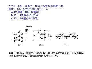
2.(2分) 在图一电路中,所有二极管均为理想元件, 则D1、D2、D3的工作状态为( )。 a. D1导通;D2、D3截止 b. D1、D3截止;D2导通 c. D1、D2截止;D3导通 3.(2分) 图二所示电路中,稳压管Dz1和Dz2的稳定电压分别为5.5V和8.5V, 正向压降均为0.5V,则负载两端的电压为( )V。
9.(2分) 在下列运算放大器的各种应用电路中, 运算放大器工作在非线性状态的电路是( ). a. 电压比较器 b.加法运算放大器 c. 反向比例放大器 二、(15分) 在如图所示的分压式偏置放大电路中,已知Ucc=12V, RB1=100kΩ,RB2=20kΩ,Rc=2kΩ,RE=1kΩ, RL=6kΩ, 晶体管的β=50,并设Rs≈0。(1)估算静态值IB,IC和UCE; (2)画出微变等效电路;(3)计算电压放大倍数Au; (4)估算放大电路的输入电阻和输出电阻.
三、(8分)求图示电路中u0与各输入电压的运算关系式.三、(8分)求图示电路中u0与各输入电压的运算关系式.
三、(8分)由运算放大器构成的模拟运算电路如下图所示,三、(8分)由运算放大器构成的模拟运算电路如下图所示, (1)试说明运算放大器A1、A2各完成何种运算? (2)求输出电压Uo等于多少?


More Related