Download

1 / 25
250 likes | 793 Vues
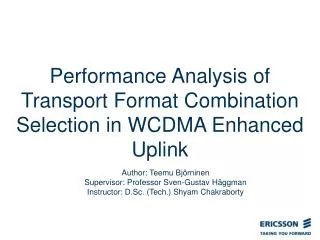
Performance analysis of Enhanced Uplink in UMTS network . Jukka Pihonen Supervisor: Prof. Riku Jäntti Instructor: Laura Koskela, M.Sc. 2008-05-30. Outline. Background Objectives and Methodology Introduction to Enhanced Uplink Introduction to Measurements Measurement Cases and Results

E N D
Performance analysis of Enhanced Uplink in UMTS network Jukka Pihonen Supervisor: Prof. Riku Jäntti Instructor: Laura Koskela, M.Sc. 2008-05-30
Outline • Background • Objectives and Methodology • Introduction to Enhanced Uplink • Introduction to Measurements • Measurement Cases and Results • Conclusions Jukka Pihonen – Master’s Thesis presentation 2008-05-30
Background • Enhanced Uplink (EUL) = High Speed Uplink Packet Access (HSUPA) = Enhanced Dedicated Channel (E-DCH) • Currently in UMTS network, the uplink transmission rate is restricted to 384 kbps • Downlink transmission rate was improved over a year ago with HSDPA, which enables up to 14.4 Mbps throughput for downlink, today 3.6 Mbps is used in commercial network • EUL balances uplink and downlink performances by enabling 1.45 Mbps uplink throughput • EUL also shortens response times and uses frequency band more effectively Jukka Pihonen – Master’s Thesis presentation 2008-05-30
Objectives and Methodology • Objectives • Introduce Enhanced Uplink • Carry out measurements using Enhanced uplink both in commercial network and in a closed laboratory network • Find out and analyze the performance of Enhanced Uplink • Compare the performance to previous R99 uplink • Methodology • Introduction to Enhanced Uplink is based on 3GPP specifications, IEEE papers and books. • Measurements were made both in laboratory and in commercial network Jukka Pihonen – Master’s Thesis presentation 2008-05-30
Introduction to Enhanced Uplink (1/4) • Enhanced Uplink is defined in 3GPP Release 6 • Combines HSDPA by enabling a fast uplink connection • EUL enhances uplink throughput first to 1.4 Mbps, later to 5.76 Mbps • Main features are • Fast Node B scheduling for uplink • Fast Hybrid Automatic Repeat Requests (HARQs) • Short Transmission Time Interval (TTI) • Multicode transmission • Introduces 5 new physical channels and 2 new MAC layer protocols Jukka Pihonen – Master’s Thesis presentation 2008-05-30
Introduction to Enhanced Uplink (2/4) • Provides following new features: • Fast Node-B scheduling • Scheduling is moved from SRNC to Node B, enables faster response times to constantly changing radio environments • Node B based scheduling keeps noise raise as high as possible -> each user gets best possible uplink throughputs • Fast HARQ • Retransmission control moved from SRNC to Node B, enables faster retransmission • Short TTI • New 2 ms TTI option to combine mandatory 10 ms TTI • Enables faster retransmissions -> reduced round trip times • 2 ms TTI was not tested • Multicode transmission • Up to 4 parallel E-DPDCHs (2 x SF2 & 2 x SF4 = 5.76 Mbps uplink throughput in Layer 1) Jukka Pihonen – Master’s Thesis presentation 2008-05-30
Introduction to Enhanced Uplink (3/4) • Introduces 5 new physical channels, 2 for uplink and 3 for downlink • Uplink channels • E-DPDCH (E-DCH Dedicated Physical Data Channel) • Carries uplink user data = E-DCH traffic channel • SF 2-256, power controlled • Number of parallel E-DPDCHs is 1-4 • E-DPCCH (E-DCH Dedicated Physical Control Channel) • Carries uplink control information • SF 256, power controlled • Carries E-DCH Transport Format Combination Identifier (E-TFCI), Retransmission Sequence Number (RSN) and a single bit called “happy bit” • Downlink channels • E-AGCH (E-DCH Absolute Grant Channel) • Carries absolute scheduling grants, SF 256 • E-RGCH (E-DCH Relative Grant Channel) • Carries relative scheduling grants, SF 128 • E-HICH (E-DCH HARQ Indicator Channel) • Carries ACKs/NACKs, SF 256 Jukka Pihonen – Master’s Thesis presentation 2008-05-30
Introduction to Enhanced Uplink (4/4) • New MAC-layer protocols • MAC-e • Between UE and Node B • Controls HARQs and scheduling • MAC-es • Between UE and SRNC • Reorders MAC-es Protocol Data Units (PDUs) in case of soft handover • Disassembles dedicated channels in RNC Jukka Pihonen – Master’s Thesis presentation 2008-05-30
Measurements were done in commercial network and in a closed laboratory network Totally four measurement cases were carried out General performance of EUL Performance of EUL in different environments Uplink performance comparison between EUL and R99 Connection setup times and round trip times Measurements in commercial network were made as a drive tests i.e. the UE was placed in a car and a certain route was driven through Measurements in laboratory were made in a stabile place, nearby Node B Laboratory has its own isolated network -> minimize external interferences Measurement unit Measurements Jukka Pihonen – Master’s Thesis presentation 2008-05-30
Long route Measurements: General performance of EUL and EUL performance in different environments Lengths: Urban 3.5 km Suburban 18.1 km Motorway 6.7 km Measurement routes (1/2) Jukka Pihonen – Master’s Thesis presentation 2008-05-30
Short route Measurement: EUL to R99 Uplink comparison Urban area is rounded with a red circle Total length 11.1 km Measurement routes (2/2) Jukka Pihonen – Master’s Thesis presentation 2008-05-30
Case 1 (1/7) • First test case was about general EUL performance • Idea was to figure out how the EUL works in practice • Test was carried out in commercial network • Results in this case covers following things • Throughputs in different layers • Happy bit status handling • MAC-e retransmission rates • E-DCH channel configurations • Tx power in different RSCP values Jukka Pihonen – Master’s Thesis presentation 2008-05-30
Case 1 (2/7) Distribution of measured samples • Best reliability between -55 dBm to -100 dBm Jukka Pihonen – Master’s Thesis presentation 2008-05-30
Case 1 (3/7) Uplink throughputs in different layers • Application layer throughput was 89 % of total carried bits in physical layer Jukka Pihonen – Master’s Thesis presentation 2008-05-30
Case 1 (4/7) Uplink application throughput and happy bit handling • EUL performed even when RSCP was -110 dBm • Happy bit started to be “happy” when RSCP reached -90 dBm • To inform unhappy, following 3 conditions must be fulfilled: • UE transmit as much scheduled data as allowed by scheduling grant • UE has enough power to transmit at higher data rate • Total buffer status in UE requires more transmission Jukka Pihonen – Master’s Thesis presentation 2008-05-30
Case 1 (5/7) Retransmission rates in MAC-e • Describes the retransmission rates, adjusted by HARQ process • Retransmission were immune to variation of RSCP value -> link adaptation worked properly Jukka Pihonen – Master’s Thesis presentation 2008-05-30
Case 1 (6/7) E-DPDCH channel configurations • The highest throughputs (up to 1.38 in Radio Link Control Layer) can be reached with 2 x SF 4 Jukka Pihonen – Master’s Thesis presentation 2008-05-30
Case 1 (7/7) Transmit power • Increases linearly, reached maximum value when RSCP -103 dBm Jukka Pihonen – Master’s Thesis presentation 2008-05-30
Case 2 (1/3) • Second test case analyzed the performance in different environments • Idea was to figure out how the EUL works in different environments (urban, suburban & motorway) • Results in this case covers following things • Uplink throughputs • Transmit powers • Retransmission rates • Happy bit status • Founds out that the performance was depended on the environment type • The best field strength was noticed in urban part, the weakest field strength was in the suburban part • Following figure shows the distribution of samples • Following table summarizes the result of this case Jukka Pihonen – Master’s Thesis presentation 2008-05-30
Case 2 (2/3) Statistics and RSCP value distribution Jukka Pihonen – Master’s Thesis presentation 2008-05-30
Case 2 (3/3) • This table summarizes the results which were gathered from different environments • Retransmission rates were immune to different environments • In all environment, the same Max UL throughput was reached • In suburban, the happy bit was most as “happy” Jukka Pihonen – Master’s Thesis presentation 2008-05-30
Case 3 (1/2) • Third test case compared R99 uplink and EUL in performance manner • Idea was to find out how much better performance can be expected with EUL compared to R99 uplink • EUL provided 2.3 times better average uplink throughput compared to R99 • EUL used 4.5 dB more transmit power • Circumstances were not stabile between routes, when EUL was measured, the average RSCP value was 4 dB higher due to better weather conditions. • increases more the power difference between EUL and R99 uplink Jukka Pihonen – Master’s Thesis presentation 2008-05-30
Case 3 (2/2) Uplink application throughputs in EUL and R99 networks • Continuous file uploading • R99 uplink was immune to variation of RSCP value • In all RSCP values, EUL provides better throughput Jukka Pihonen – Master’s Thesis presentation 2008-05-30
Case 4 • The last test case was performed in laboratory environment • Free of traffic and low interference levels. • UE was in fixed place, used one certain Node-B located nearby the UE • Purpose was to find out the connection setup times and round trip times • Results are summarized in the following table • 2 ms TTI was not tested Jukka Pihonen – Master’s Thesis presentation 2008-05-30
Conclusions • Max UL throughput was 1.38 Mbps in application layer • Scheduling worked properly keeping retransmission rates constant through the RSCP value scale • Happy bit status stayed “unhappy” until RSCP reached -85 dBm. In lower RSCP values, happy bit was more often “happy” • Best throughputs measured in urban environment • EUL provided better throughput in all RSCP values compared to R99 uplink • EUL required more transmit power compared to R99 uplink • Round trip times decreased by 9 % compared to R99/HSDPA network configuration and 40 % compared to R99/R99 network configuration Future aspects in EUL • Mobility enhances • Uplink throughput raises up to 5.76 Mbps Jukka Pihonen – Master’s Thesis presentation 2008-05-30