Comprehensive Guide to Crimping Wires for Connectors
140 likes | 774 Vues
This guide provides a step-by-step overview of the crimping process for connectors. It covers essential tasks such as obtaining pinouts, identifying proper connectors, and preparing individual wires by stripping sheathing and trimming for optimal length. Step-by-step instructions detail inserting wires into pins, crimping exposed wires and sheathing, ensuring secure connections, and correctly installing pins into the connector. Safety and precision tips are included to prevent issues with crimping and connections, making it a valuable resource for all skill levels.

Comprehensive Guide to Crimping Wires for Connectors
E N D
Presentation Transcript
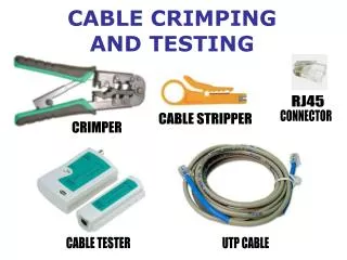
Crimping 101 SUMMARY • Get the pinouts for the desired connector and application. • Identify the proper connector and the associated pins for your application. • If necessary, strip some sheathing off the individual wires making up a cable. Twist together the exposed strands of each individual wire in the cable, straighten, and trim to proper length • Insert wire into pin. Crimp exposed wire, then wire sheathing, testing that crimp is secure after each crimp • After all crimps for cable are done, insert pins into connector in proper orientation
Step 3 If necessary, strip some sheathing off the individual wires making up a cable. Twist together the exposed strands of each individual wire in the cable, straighten, and trim to proper length (~1/4”). Here you see the 4 wires such as make up the cable for a vaisala sensor. Note that the exposed wire is straight (it’s twisted though you can’t see that in photo) and is about ¼” long. The sheaths of the individual wires are 1.5-2” long. Note: definitely don’t want more than 1/4” for the small pins that go with 8 pin umac connector. (You may need slightly more exposed wire for larger pins. In general less exposed wire is better as extra wire can block the mating pin from entering connector.
Step 4a Insert wire into pin. Side view of pin with wire inserted Lock – like fishhook, keeps pin in connector Guide tabs/rails – these guide the pin into the connector – do not crimp Tab for wire sheathing Tab for exposed wire During crimping, be careful to not crimp guide tab/rail or lock Top view of pin with wire inserted
Step 4b Crimp exposed wire, then wire sheathing, testing that crimp is secure after each crimp Be careful not to crimp these! Do first Do second For this particular wire/pin situation, 1.8mm worked for the exposed wire crimp, while 2.0 mm worked for the wire sheathing crimp. It may help to slightly manually pre-bend the sheathing tab around the wire sheath to be sure the tab goes the way you want it too.
Step 5 After all crimps for cable are done, insert pins into connector in proper orientation. Verify the crimps are good before inserting in connector – unless you have a pin puller! Guide tab/rail • The pin has tabs/rails which guide it into the connector and a lock which locks it in place. • The pin needs to be pushed into the connector far enough so that the lock catches and the pin/wire assembly cannot be pulled back out. • Pin should fit into connector easily, with minimal force lock Side view of pin with crimping done Sheath crimp Exposed wire crimp Guide tab/rail Notches for guide tabs/rails crimps lock Side view of pin with wire inserted Insertion side of connector