Supported by
Supported by . NSTX Centerstack Upgrade Project Meeting P. Titus November 2 2011. This Looks OK . Downward Component of the Force adds bending stress to the plates and welds. Can this offset be reduced?. Plate Element Model. Plate Element Model Displacements +/- .128e-3.

Supported by
E N D
Presentation Transcript
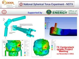
Supported by NSTX Centerstack Upgrade Project Meeting P. Titus November 2 2011
This Looks OK Downward Component of the Force adds bending stress to the plates and welds Can this offset be reduced?
Plate Element Model Displacements +/- .128e-3
Solid 45 Model – 4 Elements in Thickness Displacements +/- .133e-3 Plate Element Model Displacements +/- .128e-3
Solid 45 Wedge Model 1 Element in Thickness Solid 45 Model – 4 Elements in Thickness Displacements +/- .133e-3 Plate Element Model Displacements +/- .128e-3
Solid 45 Wedge Model- 1 Element in Thickness Displacements +.267e-4 - .804e-4 Solid 45 Model – 4 Elements in Thickness Displacements +/- .133e-3 Plate Element Model Displacements +/- .128e-3
Early: Toroidal Peaking Factor (TPF) of 2.0 400 kA Halo Static, Next Art looked at Inductive plus resistive re-distribution Mid Plane TPF = 1.05, Input TPF = 2.0 Art Updated Cal after Consultation with Stefan Gerhardt Peaking factor was a function of Halo fraction – basically TPF = 1.35 Now TPF = 1.35 at Mid Planeof Casing = Mid Plane Peaking Factor Must Be 1.6 at Strike Points Base Moment was 69,000 N-m Now Nbase Moment is 135 N-m
Stress in the G-10 Crown and Helicoil Inserts Areas of G-10 and TF Flags Due to PF1A&B+OH Vertical Force + Halo Loads Ali Zolfaghari
Added 12000lbs or 53270 N to the existing OOP torque and thermal expansion moment and bolt pretension.
This is the upper crown. The lower crown has even 50% larger tongue thickness A section through the crown piece.
This is the upper crown. The lower crown has even 50% larger tongue thickness Shear Stress
Lower CS-Skirt/OH-Cage/TF_Flag Area G-10 This bolt is threaded into a helicoil insert into G-10.
Section through the bolt G-10 shear stress below 75 MPa allowable for threads G-10 stress intensity below 150 MPa allowable