Memory System
This unit explores fundamental concepts in memory systems, focusing on the architecture and operation of RAM (Random Access Memory). It discusses the size and speed of memory, the role of registers like MAR and MDR in data transfers, and introduces types of RAM, including Static RAM (SRAM) and Dynamic RAM (DRAM). Key performance metrics such as memory access time and cycle time are defined. The unit also emphasizes design considerations for achieving optimal memory performance while managing costs.

Memory System
E N D
Presentation Transcript
Memory System Unit-IV Unit-4 : Memory System
Basic concepts (contd..) Memory Processor k -bit address bus MAR n -bit data bus k Up to 2 addressable MDR locations Word length = n bits Control lines R / W ( , MFC, etc.) Recall that the data transfers between a processor and memory involves two registers MAR and MDR. If the address bus is k-bits, then the length of MAR is k bits. If the word length is n-bits, then the length of MDR is n bits. Control lines include R/W and MFC. For Read operation R/W = 1 and for Write operation R/W = 0. Unit-4 : Memory System
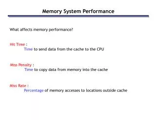
Basic concepts (contd..) • Measures for the speed of a memory: • Elapsed time between the initiation of an operation and the completion of an operation is the memory access time. • Minimum time between the initiation of two successive memory operations is memory cycle time. • In general, the faster a memory system, the costlier it is and the smaller it is. Unit-4 : Memory System
Basic concepts (contd..) • An important design issue is to provide a computer system with as large and fast a memory as possible, within a given cost target. • Several techniques to increase the effective size and speed of the memory: • Cache memory (to increase the effective speed). • Virtual memory (to increase the effective size). Unit-4 : Memory System
Semiconductor RAM memories • Random Access Memory (RAM) memory unit is a unit where any location can be addressed in a fixed amount of time, independent of the location’s address. Unit-4 : Memory System
Semiconductor RAM memories • Internal organization of memory chips: • Each memory cell can hold one bit of information. • Memory cells are organized in the form of an array. • One row is one memory word. • All cells of a row are connected to a common line, known as the “word line”. • Word line is connected to the address decoder. • Sense/write circuits are connected to the data input/output lines of the memory chip. Unit-4 : Memory System
Semiconductor RAM memories Internal organization of memory chips 7 7 1 1 0 0 • • • W 0 FF FF A • • • 0 W 1 A 1 Address Memory • • • • • • • • • • • • • • • • • • cells decoder A 2 A 3 • • • W 15 R / W Sense / Write Sense / Write Sense / Write circuit circuit circuit CS Data input /output lines: b b b 7 1 0 Unit-4 : Memory System
Semiconductor RAM memories Internal organization of memory chips 5-bit row address W 0 W 1 32 ´ 32 5-bit memory cell decoder array W 31 Sense / Write circuitry 10-bit address 32-to-1 R / W output multiplexer and CS input demultiplexer 5-bit column address Data input/output Unit-4 : Memory System
Semiconductor RAM memories • Static RAMs (SRAMs): • Consist of circuits that are capable of retaining their state as long as the power is applied. • Volatile memories, because their contents are lost when power is interrupted. • Access times of static RAMs are in the range of few nanoseconds. • However, the cost is usually high. • Dynamic RAMs (DRAMs): • Do not retain their state indefinitely. • Contents must be periodically refreshed. • Contents may be refreshed while accessing them for reading. Unit-4 : Memory System
Static Memories - SRAM • Contain circuits that retains their state as long as power is applied • Implementation • cross connect two inverters to form a latch • transistors act as switches that open or close under the control of the Word Line Unit-4 : Memory System
Static Memories - SRAM • Operation • Write: Sense/ write circuit places value on line b and compliment on b’; forces cell into correct state • Read: Activate Word Line to close switches T1 and T2 ; b carries the value of the circuit; Sense/ write circuit monitors b and b’ and set out accordingly Unit-4 : Memory System
A Static RAM Cell Unit-4 : Memory System
CMOS Memory Cell • Major advantage of very low power consumption • current flows only when the cell is being accessed • 5 volt and 3.3 volt versions • Implementation • transistor pairs forms the inverters • in state 1, point X is high • transistors T3 and T6 are on while T4 and T5 are off Unit-4 : Memory System
A CMOS Memory Cell Unit-4 : Memory System
SRAM Operation • Transistor arrangement gives stable logic state • State 1 • C1 high, C2 low • T1 T4 off, T2 T3 on • State 0 • C2 high, C1 low • T2 T3 off, T1 T4 on • Address line transistors T5 T6 form switches • Write – apply value to B and complement to B • Read – value is on line B, no rewrite required feedback Unit-4 : Memory System
SRAM - Static RAM • Bits stored in flip-flop • No charges to leak • No refreshing needed when powered - does not need refresh circuits, does not waste time refreshing • More complex cell– more transistors per cell • Larger per bit • More expensive • Faster • Used for cache memory Unit-4 : Memory System
DRAM - Dynamic RAM • Bits stored as charge in capacitors • Charges leak in milliseconds • Need periodic refreshing even when powered – read, rewrite by CPU • Need to refresh → ‘dynamic’ RAM • Simpler construction but need refresh circuits • Smaller per bit • Less expensive • Slower • Used for main memory Unit-4 : Memory System
DRAM Operation • Address line active when bit read or written • Transistor switch high – line closed (current flows) • Write • Voltage to bit line • High for 1, low for 0 • Signal (activate) address line • Transfers charge to capacitor • Read • Address line selected • transistor turns on • Charge from capacitor fed via bit line to sense amplifier • Compares with reference value to determine 0 or 1 • Capacitor charge must now be restored - rewrite – cycle time! WRITE READ Unit-4 : Memory System
R A S A ¤ A 20 - 9 8 - 0 R / W C A S Asynchronous DRAM Internal organization of a Dynamic RAM memory chip • Organized as 4kx4k array. • 4096 cells in each row are • divided into 512 groups of 8. • Each row can store 512 bytes. • 12 bits to select a row, and 9 • bits to select a group in a row. • Total of 21 bits. • Reduce the number of bits by • multiplexing row and column • addresses. • First apply the row address, RAS • signal latches the row address. • Then apply the column address, • CAS signal latches the address. • Timing of the memory unit is • controlled by a specialized unit • which generates RAS and CAS. • This is asynchronous DRAM. Row Row 4096 ´ ( 512 ´ 8 ) address decoder cell array latch CS Sense / Write circuits Column Column address decoder latch Unit-4 : Memory System
Semiconductor RAM memories(contd..) • Recall the operation of the memory: • First all the contents of a row are selected based on a row address. • Particular byte is selected based on the column address. • Suppose if we want to access the consecutive bytes in the selected row. • This can be done without having to reselect the row. • Add a latch at the output of the sense circuits in each row. • All the latches are loaded when the row is selected. • Different column addresses can be applied to select and place different bytes on the data lines. Unit-4 : Memory System
Semiconductor RAM memories(contd..) • Consecutive sequence of column addresses can be applied under the control signal CAS, without reselecting the row. • Allows a block of data to be transferred at a much faster rate than random accesses. • A small collection/group of bytes is usually referred to as a block. • This transfer capability is referred to as the fast page mode feature. Unit-4 : Memory System
Conventional DRAM Organization • d x w DRAM: • dw total bits organized as d supercells of size w bits 16 x 8 DRAM chip cols 0 1 2 3 memory controller 0 2 bits / addr 1 rows supercell (2,1) 2 (to CPU) 3 8 bits / data Unit-4 : Memory System internal row buffer
Reading DRAM Supercell (2,1) • Step 1(a): Row access strobe (RAS) selects row 2. • Step 1(b): Row 2 copied from DRAM array to row buffer. 16 x 8 DRAM chip cols 0 memory controller 1 2 3 RAS = 2 2 / 0 addr 1 rows 2 3 8 / data Unit-4 : Memory System internal row buffer
To CPU supercell (2,1) supercell (2,1) Reading DRAM Supercell (2,1) • Step 2(a): Column access strobe (CAS) selects column 1. • Step 2(b): Supercell (2,1) copied from buffer to data lines, and eventually back to the CPU. 16 x 8 DRAM chip cols 0 memory controller 1 2 3 CAS = 1 2 / 0 addr 1 rows 2 3 8 / data Unit-4 : Memory System internal row buffer internal buffer
Basic DRAM read & write • Strobe address in two steps Unit-4 : Memory System
RAS_L DRAM READ Timing RAS_L CAS_L WE_L OE_L • Every DRAM access begins at: • Assertion of the RAS_L • 2 ways to read: early or late v. CAS D A 256K x 8 DRAM 9 8 DRAM Read Cycle Time CAS_L A Row Address Col Address Junk Row Address Col Address Junk WE_L OE_L D High Z Junk Data Out High Z Data Out Read Access Time Output Enable Delay Unit-4 : Memory System Late Read Cycle: OE_L asserted after CAS_L Early Read Cycle: OE_L asserted before CAS_L
Early Read Sequencing • Assert Row Address • Assert RAS_L • Commence read cycle • Meet Row Addr setup time before RAS/hold time after RAS • Assert OE_L • Assert Col Address • Assert CAS_L • Meet Col Addr setup time before CAS/hold time after CAS • Valid Data Out after access time • Disassert OE_L, CAS_L, RAS_L to end cycle Unit-4 : Memory System
Late Read Sequencing • Assert Row Address • Assert RAS_L • Commence read cycle • Meet Row Addr setup time before RAS/hold time after RAS • Assert Col Address • Assert CAS_L • Meet Col Addr setup time before CAS/hold time after CAS • Assert OE_L • Valid Data Out after access time • Disassert OE_L, CAS_L, RAS_L to end cycle Unit-4 : Memory System