Download
1 / 13
130 likes | 267 Vues
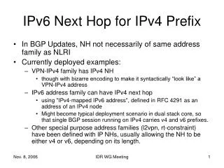
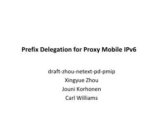
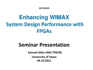
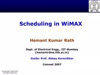
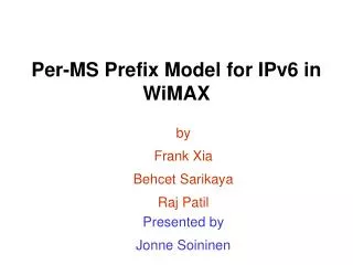
Per-MS Prefix Model for IPv6 in WiMAX. by Frank Xia Behcet Sarikaya Raj Patil. Presented by Jonne Soininen. OUTLINE. Introduction Per-MN subnet prefix model Issues Conclusions. AR. AR. BS. Host. MN. Virtual Link vs Physical Link.

E N D
Per-MS Prefix Model for IPv6 in WiMAX by Frank Xia Behcet Sarikaya Raj Patil Presented by Jonne Soininen
OUTLINE • Introduction • Per-MN subnet prefix model • Issues • Conclusions
AR AR BS Host MN Virtual Link vs Physical Link • Physical Link: Ethernet, Optical, Frame-relay, etc. These are physical interfaces on the router • An AR normally has a limited number of physical interfaces available for connectivity From the IP layer perspective, there is no difference between physical and virtual links • Virtual Link: A link that does not directly map to a physical interface • Dynamic behavior: When an MS is connected to an AR, the link is up. When an MS detaches from the AR, the link is deleted • Capacity: Hundreds and thousands of MNs connect to AR, and each MN has at least a link
Implementation of Virtual Link MN BS AR CID1 Tunnel 1 CID2 Tunnel 2 link 1 link 1 Mapping CID n Tunnel n link 2 link 2 • Each MN has one or more virtual links, such as link1 and link2 • Each link has one or more CIDs/Tunnels. For example, link 1 has several CIDs, while link 2 only has one CID • The virtual link illustrated with dotted lines consists of two segments. The MN-BS segment is the air interface part, and is identified by CID (IEEE .16). The BS-AR segment can be a wired or wireless link. GRE tunnels on a per MS basis are established between the BS and AR. • In the BS, there is a mapping between CID and Tunnel ID.
PREFIX ASSIGNMENT • Fast Router Discovery As soon as a virtual link becomes active, an AR sends an unsolicited RA • Solicited Router Advertisement The AR responds with an RA when it receive a RS via a virtual link. • Periodic Router Advertisements When a virtual link is active, periodic router advertisement SHOULD be sent by the AR. • Note: Periodic RAs should be dealt as a deployment option. They may be dropped by the AR if necessary.
NEIGHBOR DISCOVERY • Neighbor: An AR is the only neighbor for an MN on a link • NS/NA/RS/RA: As per RFC2461, No modification or adaptation is necessary • Stateless Address Autoconfiguration: As per RFC2462, No modification or adaptation is necessary • DAD: There is very low address duplication possibility; Optimistic DAD as per RFC4429 is preferable
INFORMATION MODEL Each MN and AR have a virtual link information table which includes the following elements • virtual link ID Each MN has one or more virtual links connected to an AR • Prefixes One or more prefixes assigned to the link for address configuration or renumbering • CIDs Tunnel between BS and AR can be viewed as the extension of CID. These CIDs/tunnels compose the virtual link • Optional items MTU and other items can be included
DORMANT MODE OPERATION • Efficient Dormant Mode: Link-local multicast is limited since the only nodes on the link are the MN and the AR • Virtual link maintenance when an MN is dormant: When an MS becomes dormant, the MS and AR delete all existing CIDs/tunnels, while other attributes of the links entry including prefixes are kept unchanged, When the MS becomes active again, new CIDs/tunnel are created and the link table updated
ISSUES RAISED • Per MN prefix, how to manage the prefixes? • MN mobility can cause route flip? • Are there enough prefixes?
Concern 1: Prefix Management AR AR DHCP Server DHCP client DHCP relay MS 1)Network Entry and Authentication 2) Relay-forward (Solicit) 3)Relay-reply (Advertise) DHCP server is responsible for the prefix allocation and release 4)Relay-forward (Request) 5)Relay-reply (Reply) 6)Transport connection (Virtual Link )established 7) Router Advertise 8) MLD Join 9) DAD Procedure
Concern 2: Route Flip • AR should broadcast the prefixes (MNs route information) dynamically upstream • Many MNs so high broadcast traffic • MN leaves the ASN and this causes route flip too frequently • Route Aggregation solves both problems. • For example, each AR can be assigned a /48 prefix, while an MS' /64 prefix is derived from the /48 prefix extension.
Concern 3: Enough Prefixes • There is a detailed analysis in section 2.3.1 of RFC 3314 • A total of 490 trillion (490x10^12) /64 prefixes can be assigned. This translates into around 80,000 prefixes per person on the earth today
CONCLUSIONS • Per-MN (or per-MS) prefix model fits naturally to p-t-p links • Prefixes can be managed using DHCP • There are enough prefixes (address depletion is not a concern) • No impact to host stacks if the shared prefix model is adopted in the future