Download
1 / 49
890 likes | 1.63k Vues
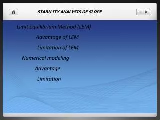
STABILITY ANALYSIS OF SLOPE. Limit equilibrium Method (LEM) Advantage of LEM Limitation of LEM Numerical modeling Advantage Limitation . Software based on Limit equilibrium Method SLIDE ( rocscience group) GALENA GEO-SLOPE GEO5

E N D
STABILITY ANALYSIS OF SLOPE Limit equilibrium Method (LEM) Advantage of LEM Limitation of LEM Numerical modeling Advantage Limitation
Software based on Limit equilibrium Method SLIDE (rocscience group) GALENA GEO-SLOPE GEO5 GGU SOILVISION
Software based on Numerical modeling PHASES2 PLAXIS FLAC-SLOPE / UDEC / PPF ANSYS FEFLOW GEOSLOPE/SIGMA SOIL-VISION
Required input properties Young modulus Poisson ratio Density Failure criterion: M-C H-B Cohesion UCS Friction angle m & s
Numerical modeling • Type of failure mechanism • Physico-mechanical behaviour of slope material • Types of analysis
Numerical modeling • Continuum modelling FEM, BEM and FDM • Discontinuum modelling DEM, UDEC • Hybrid modelling PPF,
What are the conditions of slope in the field • Simple slope with single, two or three joints • Large number of joint sets present in the slope • Heavily jointed rock slope • Waste dump / very weak rock / soil
Simple slope with single, two or three joints • large number of joint sets present in the slope • Heavily jointed rock • Waste dump / very weak rock / soil • Properties of each Joints strength • Properties of each joint set or combined properties • Properties of jointed rock mass • Properties of waste rock
Continuum modelling Continuum modeling is best suited for the analysis of slopes that are comprised of massive, intact rock, weak rocks, and soil-like or heavily jointed rock masses. Discontinuum modeling is appropriate for slopes controlled by discontinuity behaviour. • Critical Parameters: shear strength of material, constitutive criteria, water condition, insitu stress state • Advantages: Allows for material deformation and failure, model complex behaviour, pore pressures, creep deformation and/or dynamic loading can be simulated • Limitations: inability to model effects of highly jointed rock
Continuum modelling • Typical Input required Moduls of Elasticity Poision ratio Density Shear strength (cohesion and friction angle) Model Behavior
Typical Input required • Moduls of Elasticity for rock and joints • Poision ratio for rock and joints • Density • Shear strength for rock and joints • Joint behaviour • Water pressure
• Continuum modelling (water simulation) Pore water pressure Ground water table Infiltration of rain water
Discontinuum modelling • Discontinuummodeling is appropriate for slopes controlled by discontinuity behaviour • Critical Parameters: discontinuity stiffness and shear strength; groundwater characteristics; in situ stress state. • Advantages: Allows for block deformation and movement of blocks relative to each other, can modeled with combined material and discontinuity behaviour coupled with hydro - mechanical and dynamic analysis • Limitations: need to simulate representative discontinuity geometry (spacing, persistence, etc.); limited data on joint properties available
cohesion joint dilation joint friction joint joint normal stiffness joint shear stiffness
Hybrid modelling Hybrid codes involve the coupling of these two techniques (i.e. continuum and discontinuum) to maximize their key advantages. • Critical Parameters: Combination of input parameters • Advantages: Coupled finite-/distinctelement models able to simulate intact fracture propagation and fragmentation of jointed and bedded rock. • Limitations: high memory capacity;
Two-dimensional analysis versus three-dimensional analysis 2D Simulation by Geoslope software based on Finite element method 3D Simulation by Ansys software based on Finite element method
Continuum versus discontinum models 2D simulation of bench slope by FLAC based on finite difference method 3D simulation of slope 3DEC software based on discontinum modeling
Selecting appropriate zone size Different view discritized view of internal dump slope
Boundary conditions Typical recommendations for locations of artificial far-field boundaries in slope stability analyses.
Water pressure Simulation of rain water infiltration and generation of water table
Excavation sequence Show the sequential excavation
Stability / failure indicators Factor of safety Displacement ( x and Y) Shear Strain Yield Points Plastic Points unbalance force/ convergence of solution Velocity
Stability / failure indicators Factor of safety
Stability / failure indicators Displacement ( x and Y)
Stability / failure indicators Shear Strain
Stability / failure indicators Yield Points
Stability / failure indicators Velocity Vector
Stability / failure indicators unbalance force/ convergence of solution