Download
1 / 134
1.34k likes | 1.49k Vues
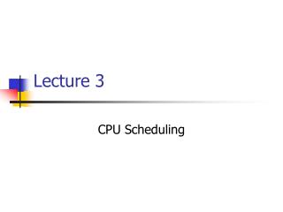
CNS 2640 Lecture 6/7 Assembled by M. Ryan Byrd. NSFNET Backbone. Stanford. ISU. BARNET. MidNet. Regional. Regional. Westnet. Regional. Berkeley. PARC. UNL. KU. UNM. NCAR. UA. Service Provided. Backbone. Stanford. ISU. BARNET. MidNet. Regional. Regional. Westnet.

E N D
NSFNET Backbone Stanford ISU BARNET MidNet Regional Regional Westnet . . . Regional Berkeley PARC UNL KU UNM NCAR UA Service Provided Backbone Stanford ISU BARNET MidNet Regional Regional Westnet Regional Berkeley PARC UNL KU UNM NCAR UA Internet Structure Recent Past Today
Numbers • www.icann.org Internet Corporation for Assigned Names and Numbers • www.arin.net is our authority and has more details • Names and numbers have been privatized. The US government used to allocate them
Popular Interior Gateway Protocols • RIP: Route Information Protocol • developed at Berkeley • distributed with Unix • distance-vector algorithm- neighbors • based on hop-count • OSPF: Open Shortest Path First • recent Internet standard • uses link-state algorithm-bcast • supports load balancing • supports authentication
IP Service Model • Packet Delivery Model • Best Effort • Global Addressing Scheme • IP Addresses
Packet Delivery Model • Connectionless (datagram-based) • Best-effort delivery (unreliable service) • packets are lost • packets are delivered out of order • duplicate copies of a packet are delivered • packets can be delayed for a long time
IP Datagram format • Version (4): currently 4 • Hlen (4): number of 32-bit words in header • TOS (8): type of service (not widely used QoS) • Length (16): number of bytes in this datagram • Ident (16): different for each datagram • Flags/Offset (16): used by fragmentation • TTL (8): number of hops this datagram has travelled • Protocol (8): demux key (TCP=6, UDP=17) • Checksum (16): of the header only • DestAddr & SrcAddr (32)
Fragmentation and Reassembly • Each network has some MTU • Strategy • fragment when necessary (MTU < Datagram) • try to avoid fragmentation at source host • refragmentation is possible • fragments are self-contained datagrams • use CS-PDU (not cells) for ATM • delay reassembly until destination host • do not recover from lost fragments • Fragment on 8 byte boundaries • Drop the last 3 bits of the offset field
Datagram Forwarding • Strategy • every datagram contains destination's address • if directly connected to destination network, then forward to host • if not directly connected to destination network, then forward to some router • forwarding table maps network number into next hop • each host has a default router • each router maintains a forwarding table
Error Control Overview • Errors occur due to • Noise or interference in the communication channel • Congestion in the network where packets musts be dropped • Error Control Strategies • Error Correcting codes (Forward Error Correction (FEC)) • Error detection and retransmission Automatic Repeat Request (ARQ)
Cyclic Redundancy Check • Add k bits of redundant data to an n-bit message. • Represent n-bit message as an n-1 degree polynomial; e.g., MSG=10011010 corresponds to M(x) = x7+ x4 + x3 + x1. • Let k be the degree of some divisor polynomial C(x); e.g., C(x) = x3+ x2 + 1.
CRC • Transmit polynomial P(x) that is evenly divisible by C(x), and receive polynomial P(x) + E(x); E(x)=0 implies no errors. • Recipient divides (P(x) + E(x)) by C(x); the remainder will be zero in only two cases: E(x) was zero (i.e. there was no error), or E(x) is exactly divisible by C(x). Choose C(x) to make second case extremely rare.
Example • Make all legal messages divisible by 3 • If you want to send 10 • First multiply by 4 to get 40 • Now add 2 to make it divisible by 3 = 42 • When the data is received .. • Divide by 3, if there is no remainder there is no error • If no error, divide by 4 to get sent message • If we receive 43, 44, 41, 40, then error • 45 would not be recognized as an error
TCP Congestion Control • Idea • assumes best-effort network • each source determines network capacity for itself • uses implicit feedback • ACKs pace transmission (self-clocking)
Algorithm: • increment CongestionWindow by one packet per RTT (linear increase) • divide CongestionWindow by two whenever a timeout occurs (multiplicative decrease)
Underlying best-effort network • drops messages • re-orders messages • delivers duplicate copies of a given message • limits messages to some finite size • delivers messages after an arbitrarily long delay
Common end-to-end services • guarantee message delivery • deliver messages in the same order they are sent • deliver at most one copy of each message • support arbitrarily large messages • support synchronization • allow the receiver to apply flow control to the sender • support multiple application processes on each host
Simple Demultiplexor (User Datagram Protocol UDP) • Unreliable and unordered datagram service • Adds multiplexing • No flow control • Endpoints identified by ports • servers have well-known ports • see /etc/services on Unix • Optional checksum • pseudo header + udp header + data • Header format
Bits 0 - 15 Bits 16 -31 Source Port Destination Port Length Checksum Data ::: UDP Header
0-15 16-31 Source Port Destination Port Sequence Number Acknowledgment Number Data Offset reserved ECN Control Bits Window Checksum Urgent Pointer Options and padding ::: Data ::: TCP Header (for contrast)
Demux Process (value of “port”) Application Application Application process process process Ports Queues Port 3100 Port 3000 Packets Port 2000 demultiplexed UDP Packets arrive
Overview • Connection-oriented • Byte-stream • sending process writes some number of bytes • TCP breaks into segments and sends via IP • receiving process reads some number of bytes • Full duplex • Flow control: keep sender from overrunning receiver • Congestion control: keep sender from overrunning network • Read p 272-287 in Cisco book
Src Port Dest Port SequenceNum Acknowledgement 0 HdrLen Flags Advertised (4) (6) (6) Window CheckSum UrgPtr options (variable) data TCP Segment Format • Each connection identified with 4-tuple: • <SrcPort, SrcIPAddr, DstPort, DstIPAddr> • Sliding window + flow control • Acknowledgment, SequenceNum, AdvertisedWindow • Flags: SYN, FIN, RESET, PUSH, URG, ACK • Checksum: pseudo header + tcp header + data
Active Participant Passive Participant SYN, SequenceNum = x SYN + ACK, SequenceNum = y, Acknowledgement = x + 1 ACK, Acknowledgement = y + 1 TCP Connection Establishment and Termination • Three-Way Handshake-random number so that packets from consecutive sessions are unique
Sliding Window Revisited • Each byte has a sequence number • ACKs are cumulative
Sliding Window (details) • Sending side • LastByteAcked LastByteSent • LastByteSent LastByteWritten • bytes between LastByteAcked and LastByteWritten must be buffered • Receiving side • LastByteRead < NextByteExpected • bytes between NextByteRead and LastByteRcvd must be buffered
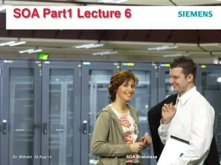
ARP D ff.ff.ff.ff.ff.ff SP 128.187.171.2 SH fe.34.56.32.d5.29 DP 128.187.174.10 DH 0.0.0.0.0.0 D ff.ff.ff.ff.ff.ff SP 128.187.171.2 SH fe.34.56.32.d5.29 DP 128.187.174.10 DH 0.0.0.0.0.0 D 128.187.174.10 D 44.fe.34.56.32.d5 S 128.187.171.2 S fe.34.56.32.d5.29 D 128.187.174.10 D 44.fe.34.56.32.d5 S 128.187.171.2 S fe.34.56.32.d5.29 D ff.ff.ff.ff.ff.ff SP 128.187.171.2 SH fe.34.56.32.d5.29 DP 128.187.174.10 DH 0.0.0.0.0.0 D ff.ff.ff.ff.ff.ff SP 128.187.171.2 SH fe.34.56.32.d5.29 DP 128.187.174.10 DH 0.0.0.0.0.0 D fe.34.56.32.d5.29 SP 128.187.174.10 SH 44.fe.34.56.32.d5 DP 128.187.171.2 DH fe.34.56.32.d5.29 D fe.34.56.32.d5.29 SP 128.187.174.10 SH 44.fe.34.56.32.d5 DP 128.187.171.2 DH fe.34.56.32.d5.29 173 171 Switch H1 H2 H3 H7 H8 H9 56.47.ef.c6.34.78 172 174 H4 H5 H6 H10 H11 H12 55.7e.c6.11.78.99 H10= IP 128.187.174.10, Ethernet 44.fe.34.56.32.d5
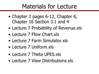
ARP D ff.ff.ff.ff.ff.ff SP 128.187.171.2 SH fe.34.56.32.d5.29 DP 128.187.174.10 DH 0.0.0.0.0.0 D 128.187.174.10 D 56.47.ef.c6.34.78 S 128.187.171.2 S fe.34.56.32.d5.29 D 128.187.174.10 D 44.fe.34.56.32.d5 S 128.187.171.2 S 55.7e.c6.11.78.99 D ff.ff.ff.ff.ff.ff SP 128.187.171.2 SH 55.7e.c6.11.78.99 DP 128.187.174.10 DH 0.0.0.0.0.0 D 55.7e.c6.11.78.99 SP 128.187.174.10 SH 44.fe.34.56.32.d5 DP 128.187.171.2 DH 55.7e.c6.11.78.99 D fe.34.56.32.d5.29 SP 128.187.174.10 SH 56.47.ef.c6.34.78 DP 128.187.171.2 DH fe.34.56.32.d5.29 173 171 Router H1 H2 H3 H7 H8 H9 56.47.ef.c6.34.78 172 174 H4 H5 H6 H10 H11 H12 55.7e.c6.11.78.99 H10= IP 128.187.174.10, Ethernet 44.fe.34.56.32.d5
IP Routing Definitions and Terminology • Routers are Layer 3 (Network Layer) devices • Traditionally routers were called gateways • Routers are used for information exchange within a group of networks under the same administrative authority and control (Autonomous Systems) • Routing can be both dynamic and static • Routing involves the determination of routing paths and the transport of information groups (packets) through an internetwork
RIP Packet Fields Description • Command: • Indicates that the packet is a request or a response. The request command requests the responding system to send all or part of its routing table. Destinations for which a response is requested are listed later in the packet. The response command represents a reply to a request or, more frequently, an unsolicited regular routing update. In the response packet, a responding system includes all or part of its routing table. Regular routing update messages include the entire routing table. • Version number: • Specifies the RIP version being implemented. With the potential for many RIP implementations in the Internet, this field can be used to signal different, potentially incompatible, implementations.