Understanding Basic Circuit Definitions and Concepts
Explore the fundamentals of circuits, current flow, electromotive force, resistance, and connections in this comprehensive guide. Learn about symbols, Ohm's Law, resistors, and practical applications.

Understanding Basic Circuit Definitions and Concepts
E N D
Presentation Transcript
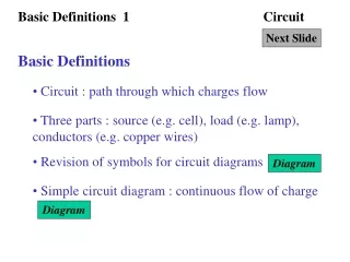
Basic Definitions 1 Circuit Next Slide Basic Definitions • Circuit : path through which charges flow • Three parts : source (e.g. cell), load (e.g. lamp), conductors (e.g. copper wires) • Revision of symbols for circuit diagrams Diagram • Simple circuit diagram : continuous flow of charge Diagram
Basic Definitions 2 Circuit Next Slide Basic Definitions • Conventional current : flow of +ve charge • Flow of electrons : flow of -ve charge Diagram • Current : rate of flow of charge with respect of time, through the circuit
Basic Definitions 3 Circuit Next Slide Flow of current • Flow of electrons due to the battery • Conservation of energy : Chemical energy in the battery Electrical potential energy in the electrons Light and internal energy of the lamp Diagram
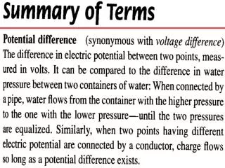
Basic Definitions 4 Circuit Next Slide Electromotive force and potential differenece • Electromotive force (e.m.f.) of a battery : the potential energy given to every coulomb of charge passing through the battery • Potential difference (p.d.) of a lamp : the electrical potential energy given out and changed into other form by one coulomb of charge passing through the lamp
Basic Definitions 5 Circuit Next Slide Electromotive force and potential differenece • Example 1 Calculation • Example 2 Calculation • Ammeter : measure current Diagram • Voltmeter : measure e.m.f. or p.d. Diagram
Ohm’s law 1 Circuit Next Slide Relationship between I and V • Experiment to investigate the relationship between I and V Calculation • Ohm’s Law : • the p.d. across the ends of a conductor is directly proportional to the current flowing through it, provided that the temperature and other physical conditions are constant
Ohm’s law 2 Circuit Next Slide Relationship betweenI and V • Definition of Resistance : (slope of V-I graph) • Experiment to demonstrate the restriction of Ohm’s law Calculation
Resistance Circuit Next Slide Resistance and resistors • Resistance is directly proportional to its length and inversely proportional to its cross-sectional area. Diagram • Resistor : device providing resistance Photo • Variable resistor : device providing variable resistance Photo
Resistor Circuit Next Slide Different kinds of connection • Change the circuit with 2 or more resistors to a simple circuit with only 1 resistor (equivalent resistance) • Resistors in series Calculation Calculation • Resistors in parallel • Example 1 Calculation • Example 2 Calculation
Applications Circuit Next Slide Short circuit and connection of cells • Short circuit Diagram • Different connection of cells Diagram • Internal resistance : • the resistance of the battery which also requires a p.d. to drive a current
cell ammeter battery voltmeter resistor switch lamp push switch Back to Basic Definitions 1 Circuit Click Back to • Revisions of symbols for circuit diagram
Back to Basic Definitions 1 Circuit Click Back to • A simple circuit is shown below • A continuous flow of charge is maintained.
electron flow current flow Back to Basic Definitions 2 Circuit Click Back to • Electrons (-ve charge) flow from -ve terminal through the lamp to the +ve terminal • Current (+ve charge) flows from +ve terminal through the lamp to the -ve terminal
Basic Definitions 3 Circuit Next Slide • When the electrons leave the -ve terminal of the cell, they contain certain amount of electrical potential energy. • When they pass through the lamp, the electrical potential energy changes into light and internal energy. • After passing through the lamp, they contain no electrical potential energy. Refill of energy happens when they pass through the cell again.
Energy of electrons Basic Definitions 3 Circuit Next Slide • The electrical energy stored inside the electrons can be summarised in the following diagram.
potential Back to Basic Definitions 3 Circuit Click Back to • The potential in the circuit can be summarised in the following diagram.
e.m.f. 2 V 0.4 A Basic Definitions 5 Circuit Next Slide • A cell with e.m.f. 2 V is connected to a lamp with current 0.4 A as shown in the following diagram. (a) What is the amount of charge passing the lamp in 4 s? (b) What is the p.d. across the lamp? (c) What is the amount of energy used up by the lamp in 4 s?
2 J of energy is given to each coulomb of charge passing through 0.4 A 2 J of energy is used up for each coulomb of charge passing through Back to Basic Definitions 5 Circuit Click Back to
e.m.f. 6 V 1 A p.d. 4 V M N Basic Definitions 5 Circuit Next Slide • A cell with e.m.f. 6 V is connected to 2 lamps with current 1 A as shown in the following diagram. The p.d. of lamp N is 4 V. (a) What is the p.d. across another lamp? (b) Which lamp is brighter?
e.m.f. 6 V p.d. 4 V p.d. 2 V 2 J of energy is used up for each coulomb of charge passing through 4 J of energy is given to each coulomb of charge passing through Back to Basic Definitions 5 Circuit Click Back to (a) By conservation of energy, p.d. = 6 V - 4 V = 2 V (b) The lamp with p.d. 4 V is brighter.
Back to Basic Definitions 5 Circuit Click Back to • An ammeter is connected in a circuit as shown in the following figure.
Back to Basic Definitions 5 Circuit Click Back to • A voltmeter is connected in a circuit as shown in the following figure.
battery rheostat eureka ammeter voltmeter Ohm’s law 1 Circuit Next Slide • The relation between the current and the p.d. across a conductor (eureka wire) could be investigated by the following circuit (ammeter-voltmeter method)
p.d. (V) p.d. (V) current (A) 0.8 0.2 1.6 0.4 2.4 0.6 3.3 0.8 4.2 1.0 0 current (A) Back to Ohm’s law 1 Circuit Click Back to • Rheostat is used to vary the magnitude of current. • The result is shown in the following table . • p.d. current • Slope of the graph is defined as resistance
battery rheostat Light bulb ammeter voltmeter Ohm’s law 2 Circuit Next Slide • We use the ammeter-voltmeter method to investigate the current and p.d. across a lamp as shown.
p.d. (V) Ohm’s law is only obeyed initially 0 current (A) Back to Ohm’s law 2 Circuit Click Back to • The graph of p.d. vs. current is shown. • As temperature rises, the resistance of the lamp increases.
A A L 2 L Resistance : R Resistance : 2 R A 2A L L Resistance : R Resistance : R/2 Back to Resistance Circuit Click Back to • Resistance R Length L : • Resistance R 1/Cross-sectional A :
Back to Resistance Circuit Click Back to • Some common resistors are shown in the following photo :
Resistance Circuit Next Slide • Two different variable resistors are shown in the following photos
current Back to Resistance Circuit Click Back to • Structure of rheostat is shown in the following diagram. • The longer the resistance wire the larger the resistance.
original circuit equivalent circuit e.m.f. V e.m.f. V I I I I I I R (equivalent resistance) V V Resistor Circuit Next Slide • Equivalent resistance should have the same current (I) and p.d. (V)
Back to Resistor Circuit Click Back to • The current I is the same at all points throughout the circuit. • The equivalent resistance of two or more resistors connected in series is the sum of the individual resistance.
original circuit equivalent circuit e.m.f. V e.m.f. V I I I I I V R (equivalent resistance) V V Resistor Circuit Next Slide • The circuit with R (equivalent resistance) should have the same current (I) and p.d. (V) as the original circuit.
Back to Resistor Circuit Click Back to • The p.d. across each resistors are the same as the e.m.f. of the cell V.
e.m.f. 9 V 2 4 Resistor Circuit Next Slide • A cell with e.m.f. 9 V is connected to two resistors 2 and 4 in series. Find the current , the p.d. across the 2 resistor and the p.d. across the 4 resistor.
original circuit equivalent circuit e.m.f. 9 V e.m.f. 9 V I I I 2 4 R = 2 + 4 = 6 9 V Resistor Circuit Next Slide • The circuit is changed into a circuit with 1 equivalent resistor.
Back to Resistor Circuit Click Back to
e.m.f. 12 V 3 6 Resistor Circuit Next Slide • A cell with e.m.f. 12 V is connected to two resistors 3 and 6 in parallel. Find the main current , the current through the 3 resistor and the current through the 6 resistor.
original circuit equivalent circuit e.m.f. 12 V e.m.f. 12 V I I 3 I R = 2 V 6 Resistor Circuit Next Slide • The circuit is changed into a circuit with 1 equivalent resistor.
Back to Resistor Circuit Click Back to
copper wire (short circuit) Back to Applications Circuit Click Back to • A short length of copper wire is connected across the battery (or the cell). • The wire has very small resistance and draws a large amount of current (parallel connection). • It is called short circuit and the wire becomes very hot as well as the lamp dies out. It is very dangerous and may cause fire.
e.m.f. = 4.5 V e.m.f. = 1.5 V Back to Applications Circuit Click Back to • Cells (each 1.5 V) in series (larger e.m.f.) • Cells (each 1.5 V) in parallel (the same e.m.f. as one cell)


![[Series Circuit]](https://cdn1.slideserve.com/2747272/series-circuit-dt.jpg)