Download
1 / 86
980 likes | 1.44k Vues
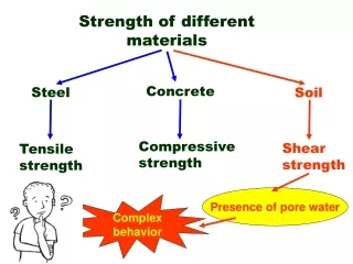
Steel. Concrete. Soil. Compressive strength. Shear strength. Tensile strength. Presence of pore water. Complex behavior. Strength of different materials. T. Area, A. F. T. R. W. W. . F. T. LOAD. Soil Surface. Soil Element. Soil Mass. Bedrock. LOAD. σ 1. σ 1. σ 2. σ 3.

E N D
Steel Concrete Soil Compressive strength Shear strength Tensile strength Presence of pore water Complex behavior Strength of different materials
T Area, A
F T
R W W F T
LOAD Soil Surface Soil Element Soil Mass Bedrock
LOAD σ1
σ1 σ2 σ3 σ3 σ2 σ1
σ1 2-D Θ σ1
σf τf Θ
Embankment Strip footing Failure surface Mobilized shear resistance Shear failure of soils Soils generally fail in shear At failure, shear stress along the failure surface (mobilized shear resistance) reaches the shear strength.
Retaining wall Shear failure of soils Soils generally fail in shear
Mobilized shear resistance Failure surface Shear failure of soils Soils generally fail in shear Retaining wall At failure, shear stress along the failure surface (mobilized shear resistance) reaches the shear strength.
failure surface Shear failure mechanism The soil grains slide over each other along the failure surface. No crushing of individual grains.
Shear failure mechanism At failure, shear stress along the failure surface () reaches the shear strength (f).
failure envelope Friction angle Cohesion f c Mohr-Coulomb Failure Criterion(in terms of total stresses) f is the maximum shear stress the soil can take without failure, under normal stress of .
’ failure envelope Effective cohesion Effective friction angle f c’ ’ ’ Mohr-Coulomb Failure Criterion(in terms of effective stresses) u = pore water pressure f is the maximum shear stress the soil can take without failure, under normal effective stress of ’.
f ’f tan ’ frictional component ’ cohesive component c’ c’ ’f ' Mohr-Coulomb Failure Criterion Shear strength consists of two components: cohesive and frictional. c and are measures of shear strength. Higher the values, higher the shear strength.
s’1 s’ s’3 s’3 t q s’1 Soil element Mohr Circle of stress Resolving forces insandtdirections,
t s’ Mohr Circle of stress
t (s’, t) q s’ PD = Pole w.r.t. plane Mohr Circle of stress
Failure surface Y Y X X Soil elements at different locations X ~ failure Y ~ stable Mohr Circles & Failure Envelope ’
c c Y c+ Initially, Mohr circle is a point Mohr Circles & Failure Envelope The soil element does not fail if the Mohr circle is contained within the envelope GL c
As loading progresses, Mohr circle becomes larger… c c .. and finally failure occurs when Mohr circle touches the envelope Mohr Circles & Failure Envelope GL Y c
(s’, tf) (90 – q) q Therefore, 90 – q + f’ = q q = 45 + f’/2 PD = Pole w.r.t. plane Orientation of Failure Plane Failure envelope f’ s’
v v’ u h h’ + u X X X t effective stresses total stresses s or s’ h’ v’ h v u Mohr circles in terms of total & effective stresses =
v v’ u h h’ + u X X X Failure envelope in terms of effective stresses Failure envelope in terms of total stresses t f’ f effective stresses total stresses c’ c s or s’ h’ v’ h v u Failure envelopes in terms of total & effective stresses = If X is on failure
t ’v = s’1 Failure envelope in terms of effective stresses ’h = s’3 effective stresses (s’1 - s’3)/2 X c’ f’ X is on failure ’3 ’1 s’ (s’1+ s’3)/2 c’ Cotf’ Therefore, Mohr Coulomb failure criterion with Mohr circle of stress
Laboratory tests on specimens taken from representative undisturbed samples Field tests • Most common laboratory tests to determine the shear strength parameters are, • Direct shear test • Triaxial shear test • Vane shear test • Torvane • Pocket penetrometer • Fall cone • Pressuremeter • Static cone penetrometer • Standard penetration test Determination of shear strength parameters of soils (c, forc’, f’) Other laboratory tests include, Direct simple shear test, torsional ring shear test, plane strain triaxial test, laboratory vane shear test, laboratory fall cone test
A representative soil sample z z svc + Ds svc shc shc shc shc svc svc + Ds After and during construction Before construction Laboratory tests Field conditions
svc + Ds shc shc Traxial test 0 svc svc + Ds svc shc shc 0 0 t Direct shear test svc 0 t svc Representative soil sample taken from the site Step 1 Set the specimen in the apparatus and apply the initial stress condition Laboratory tests Simulating field conditions in the laboratory Step 2 Apply the corresponding field stress conditions
DIRECT SHEAR TEST First Test Second Test Third Test τf τf Shear Stress, τ(kPa) τf c Normal Stress, σn(kPa)
Piston (to apply deviatoric stress) Failure plane O-ring impervious membrane Soil sample Soil sample at failure Porous stone Perspex cell Water Cell pressure Pore pressure or volume change Back pressure pedestal Triaxial Shear Test
TRIAXIAL COMPRESSION TEST diameter length
TRIAXIAL COMPRESSION TEST loading ram air release valve plexiglas chamber loading cap water supply for cell (confining) pressure latex sleeve drainage or pore water pressure measurement specimen porous disc pedestal
Sampling tubes Sample extruder Triaxial Shear Test Specimen preparation (undisturbed sample)
Setting up the sample in the triaxial cell Edges of the sample are carefully trimmed Triaxial Shear Test Specimen preparation (undisturbed sample)
Sample is covered with a rubber membrane and sealed Cell is completely filled with water Triaxial Shear Test Specimen preparation (undisturbed sample)
Proving ring to measure the deviator load Dial gauge to measure vertical displacement Triaxial Shear Test Specimen preparation (undisturbed sample)
∆σ σ3 σ3 σ3 ∆σ Plan View of Specimen Side View of Specimen
deviatoric stress ( = q) c Step 2 Step 1 c c c c c+ q c Under all-around cell pressure c Shearing (loading) yes no yes no Consolidated sample Undrained loading Drained loading Unconsolidated sample Types of Triaxial Tests Is the drainage valve open? Is the drainage valve open?
Step 2 Step 1 Under all-around cell pressure c Shearing (loading) Is the drainage valve open? Is the drainage valve open? CD test UU test yes no yes no Consolidated sample Undrained loading Drained loading Unconsolidated sample CU test Types of Triaxial Tests
= + Total, s Effective, s’ Neutral, u sVC s’VC =sVC shC s’hC =shC 0 Drainage Drainage Drainage sVC + Ds sVC + Dsf s’V =sVC +Ds = s’1 shC shC s’h =shC = s’3 0 0 s’Vf =sVC +Dsf= s’1f s’hf =shC = s’3f Consolidated- drained test (CD Test) Step 1: At the end of consolidation Step 2: During axial stress increase Step 3: At failure
Shear Stress, τ (kPa) τf c σ1 σ1 σ3 σf ∆σ ∆σ σ1 ∆σ Normal Stress, σn(kPa)
TRIAXIAL COMPRESSION TEST Shear Stress, τ (kPa) c Normal Stress, σn(kPa)
TRIAXIAL COMPRESSION TEST Shear Stress, τ (kPa) specimen Θ failure plane R c C R R Θ σ3 σ1 Normal Stress, σn(kPa)
TRIAXIAL COMPRESSION TEST To follow the trig we label the vertices: ABC = 90 so ACB = 90 - and DBC = ’s EBC & BCF are both isosceles & EBF is 90. EFB = 90 – Θ & BCF =180 – 2(90- Θ) = 2Θ DCB = 180 – 2Θ = 90 - Rearranging: Shear Stress, τ (kPa) B τf Θ c 2Θ F E Θ A D Normal Stress, σn(kPa) C σ3 σf σ1