Download
1 / 27
270 likes | 376 Vues
ILC positron Source meeting Wednesday 27 - Friday 29 September 2006 Rutherford Appleton Laboratory. Alessandro Variola For the L.A.L. Orsay group Brisson V., Chehab R., Chiche R., Cizeron R., Fedala Y., Jacquet-Lemire M., Jehanno D., Soskov V., Variola A., Vivoli A., Zomer F .,.

E N D
ILC positron Source meetingWednesday 27 - Friday 29 September 2006Rutherford Appleton Laboratory Alessandro Variola For the L.A.L. Orsay group Brisson V., Chehab R., Chiche R., Cizeron R., Fedala Y., Jacquet-Lemire M., Jehanno D., Soskov V., Variola A., Vivoli A., Zomer F.,
LAL ActivitiesWhat are we doing? • R&D on a high finesse optical cavity • Posipol scheme • Studies on channeling for the conventional solution
Present R&D at Orsay (funded by EUROTEV & IN2P3:CNRS) • 2 Goals: 1 operate a very high finesse Fabry-Perot cavity in pulsed regime • 2 mirrors cavities Gain: 104-105 • Started in sept 2005 2 reduction of the laser beam size (waist) • 4 mirrors non-planar cavity • Setup started in sept. 2006
MIRA 900P Pump laser Verdi 6W AOM Shifter AOM EOM fc fr mirror fcwedge Generator Demodulator fc GTI fr Feedback System Optical Scheme FREP Coarse tuning: 1. Mirror motor Fine tuning” 1. Mirror PZT 2. AOM FC Coarse tuning: 1.Wedge 2. GTI Fine tuning: 1. AOM-shifter
Digital Feedback Scheme 8 DAC : 14bits 125 Msps 8 ADC: 14 bits 105Msps fpga latency=60ns
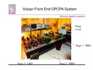
Present status Experiment setup.Laser & Cavity installed
Cavity aligned • Error signals have been measured with a ’small finesse ’ cavity (3000) Errorsignal Signal transmitted by the cavity Present activity: reduction of the noiseof the error signal and implementationof a feedback control of the small finessecavity Manpower: 1 physicist, 2 engineers, 1 tech. Full time
4 mirror cavities(R&D in 2006-2007) • The mechanical tolerances • The eigen modes • The polarisation transport • 2 extra topics( possible futur R&D) • Effect of strong laser beam focusing on cavity modes • Effect of high beam power inside the cavity
Mechanical tolerances for 4 mirrors cavity • Mirror misalignment sources • Residual precision of the installation: ~1/100 mrad, 1/100 mm • Environmental motion (vibrations, thermal…): <mrad, mm • 5 degrees of freedom per mirror Dx, Dy, Dz, Dax, Day, (of the mirror’scentres) CALCULATION: • Compute the max. displacement of the optical axis for all combinations of misalignments. rel. precision check~10-3 • Results forw0 0: with 4m optical path, 6cm between 2 adjacent mirror centres • Dxi=±0.1mm; Daxi=±0.1mrad • plane mirrors: 0.6mm • on spherical mirrors: 1.1mm • At beam waist: 0.3mm: 0.5mrad High mechanical stability [as expected] • Negligible effects of the environment a priori
R R L astigmatism 2D cavity 3D cavity astigmatismreduced wx,wy versus z R=L(1-10-2) Astigmatism mm Spher. mirrorsposition
3D cavity in a `quasi cubic’ configuration • 21 SiO2/Ta2O5 double layersCavity gain 105 • DS3=10-6 forq=5o and Dq=10mrad [4m optical path] Checking the modes calculations: Spherical mirror ok. Not spherical mirror=> problems in the waist • DS3 much less sensitive to mirror disorientations : • 4 mirror non planar cavity = good solution for waist and polarisation
4 mirrors non-plannar cavity Cavity vessel under construction in the LALworkshop Cw laser diode inextended cavity config (optical feedback forseen) In test at Orsay since 2 weeks Manpower: 1PhD. & 1 technician full time
Posipol scheme: we are working on a proposal for a unique “lepton source” ERL based 1) We have a Post Doc !!!!!! Conventional positron source Linac 6 GeV Linac 4.75 GeV Positron damping ring Target Post Acceleration 250 MeV Capture
Beam STATISTICS +++Right-going photon 25034 macro particles 1.562D+09 real Average (t,x,y,s) 4.000D-04 5.161D-08 1.431D-08 4.002D-04 m R.m.s. (t,x,y,s) 1.138D-17 8.025D-06 4.693D-06 1.711D-04 m Min (t,x,y,s) 4.000D-04 -3.212D-05 -2.013D-05 -2.618D-04 m Max (t,x,y,s) 4.000D-04 3.005D-05 2.815D-05 1.070D-03 m Average (En,Px,Py,Ps) 1.474D+07 1.699D+01 3.052D+01 1.474D+07 eV R.m.s. (En,Px,Py,Ps) 9.279D+06 2.658D+03 2.672D+03 9.279D+06 eV Min (En,Px,Py,Ps) 3.095D+02 -7.827D+03 -8.248D+03 3.082D+02 eV Max (En,Px,Py,Ps) 2.987D+07 8.207D+03 8.557D+03 2.987D+07 eV Stokes (|Xi|,Xi1,Xi2,Xi3) 0.00709 0.00128 0.00675 0.00175 ERL solution Can we compensate the charge reduction with bunch compression? • Laser power density 1.90349132D+21 • Laser pulse Energy [Joule]= 6.00000000D-01 • Laser pulse length [m]= 2.40000000D-04 • Laser pulse wavelength [m= 1.06000000D-06 • Laser waist size [m]= 1.00000000D-05 • Laser Rayleigh length [m]= 2.96376665D-04 • Compton cut off [x beam energy]= 2.27627018D-02 • Beam Energy [eV]= 1.30000000D+09 • Particles per bunch9.36000000D+09 • Collision beta function x= 1.60000000D-01 • Collision beta function y= 1.60000000D-01 • Beam size sigma x [m] = 1.00000000D-05 • Beam size sigma y [m] = 1.00000000D-05 • Beam length sigma z [m] = 2.00000000D-04 • Emittance x= 6.25000000D-10 • Emittance y= 6.25000000D-10 • Energy Spread= 3.00000000D-03 • Collision angle [rad]= 8.72664626D-02 • *********************************** • ***********************************
Polarised positron source – Compton cavities + ERL Elecrton re-circulation Linac 1.5 GeV Linac 4.75 GeV Positron damping ring Compton cavities + bunch compressor Target Post Acceleration 250 MeV Capture
a possible example ERL : 100 re injection if 1 damping ring scheme. 50 if double damping ring scheme Elecrton re-circulation Linac 1.5 GeV Linac 4.75 GeV Positron damping ring Compton cavities + bunch compressor Target Post Acceleration 250 MeV Capture 200 ms 100 ms 5640ms RF cooling 4360ms zoom 1 ms 5640ms 282ms cooling 4360ms 282ms zoom Average current = (1.8 nC x 282000 x 5 A) = 2.5 mA Peak current = (1.8nC x60) / 3 ms = 36 mA 3ms 1 ring filling @ 20 MHz X 47 3ms 3ms 20 MHz : 60 bunches 282ms
Two sources. One source every damping ring If damping rings in the same location ….…new scenarios: Electron polarised (unpolarised) source Polarised positron source – Compton cavities + ERL. (Splitting = Multi-injection in both rings) Positron damping ring Elecrton re-circulation Linac 1.5 GeV Linac 4.75 GeV Compton cavities + bunch compressor Target Post Acceleration 250 MeV Electron damping ring Capture Linac 5 GeV The first 1.5 GeV linac can be substituted with a 6 GeV one to have both sources
Electron polarised (unpolarised) source Conventional & Polarised source – Compton cavities + ERL. Damping rings in the same location (splitting) Electron re-circulation Positron damping ring Linac 1.5 / 6 GeV Linac 4.75 GeV Electron damping ring Advantage : e+ pol & unpol Linac 5 GeV But positron injection takes not more than 100 msec. The remaining 100 msec are enough for electron cooling, so we can split electron and positron injection in time and unify the electron and positron linacs :
IF DAMPING RINGS @ THE SAME LOCATION Electron polarised (unpolarised) source Conventional & Polarised source – Compton cavities + ERL. Damping rings in the same location (splitting…why not also for the conventional solution) Elecrton re-circulation Positron damping ring Linac 1.5 / 5 / 6 GeV Linac 4.75 GeV Electron damping ring Advantage : e- e+ pol & unpol with 1 LINAC of 10 GeV 1 Complex !!!! Moreover, if we can re-circulate and split the first Linac we can avoid the second one
IF DAMPING RINGS @ THE SAME LOCATION Electron polarised (unpolarised) source Conventional & Polarised source – Compton cavities + ERL. Damping rings in the same location (splitting) => e+,e- pol / non pol Positron damping ring Linac 1.25 GeV Linac 1.25 / 1.5 GeV Electron damping ring Advantage : e- e+ pol & unpol with 1 LINAC of 6.25 GeV Linac 3.5 GeV Electron re-circulation Disrupted electrons and polarised positrons are re-circulated in the same train (deceleration for electrons and acceleration for positrons) All this complex can be accommodated inside the damping rings Positron re-circulation
In the future : we would like to study the channeling option for the conventional source • UNPOLARIZED SOURCES • - an amorphous target with high Z submitted to an unpolarized e- beam of high energy [conventional] • - a crystal source made of a crystal aligned on one of its axes (radiator) and of an amorphous W disk (converter) placed after it. = Hybrid • THE Hybrid SOURCE • Pair production in the same crystal or in an amorphous disk put after the crystal (preferably) • The beam aligned on one of the crystal axes (where the potential is strong). • Experiments made at CERN, KEK • Simulations showed less deposited energy than in equivalent (e+ yield) amorphous target
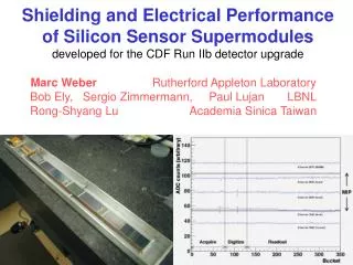
RESULTS OF WA 103 (10 GeV) • e+ yield in large momentum (150 MeV/c) and angular (30°) domains. • measured e+ yield in a (pL,pT) diagram; the case corresponds to a 8 mm crystal and a 10 GeV incident energy. Example of absolute rate : W crystal [<111> orientation], 8mm thick, the yields have been measured in (pL,pT) domains.. For 6GeV : Yield plus ~ 15% Energy loss (heating) minus ~40 %
Outlook • We are progressing in parallel with R&D of 2-mirrors and 4-mirrors cavities. - 2mirrors = 1st error signal, low finesse. - 4mirrors = evaluation of the modes and polarisation. Plans for the mechanical set-up. 1st test with CW laser • We are starting to evaluate a new scheme for the Compton source. The new idea seems promising • In the future we would like to study the impact of the channeling for the conventional source