Download
1 / 29

E N D
Prepared By : Prepared By : Mazadul Hasan sheshir ID: 2010000400008 13thBatch (session 2009-2013) Department : Wet Processing Technology Email: mazadulhasan@yahoo.com Blog : www. Textilelab.blogspot.com (visit) Southeast University Department Of Textile Engineering I/A 251,252 Tejgaon Dhaka Bangladesh
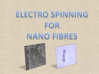
Background Polymer nanofibers are in demand for a broad range of applications including nanoscaled reinforcement, tissue engineering, speciality filters, sensors, they may also serve as templates for the preparation of nanotubes.
Electrospinning Ultrathin polymer nanofibers with diameters down to a few nanometers are accessible via the electrospinning process. It involves the application of a strong electric field to a pendent drop of a polymer solution or polymer melt. A jet is ejected and moves towards the counter electrode if the electrostatic forces overcome the surface and viscous forces. A broad range of polymers including polyamides, polylactides, cellulose derivatives, water soluble polymers such as polyethyleneoxide, polymer blends or polymers containing solid nanoparticles or functional small molecules can be electrospun.
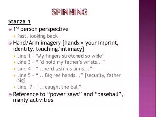
Nanofibers via electrospinning A proper choice of processing parameters such as the surface tension, the viscosity and conductivity, the concentration of the solutions, molecular weights, applied fields and electrode configurations allows to produce fibers with diameters down to a few nanometers. Nanofibers obtained by electrospinning
Current activities 1. Evaluation of the intrinsic order of the nanofibers including crystal orientation 2. Control of surface topology of the fibers via phase separation processes initiated during electrospinning 3. Introduction of functional elements such as catalysts, semi-conductor quantum structures, metal nanoparticles 4. Tissue engineering using biodegradable polymers
Current activities Orientational order in polylactide nanofibers, nanofibers with specific morphology
Electrospinning Electrospinning uses an electrical charge to draw very fine (typically on the micro or nano scale) fibres from a liquid. Electrospinning shares characteristics of both electrospraying and conventional solution dry spinningof fibers. The process is non-invasive and does not require the use of coagulation chemistry or high temperatures to produce solid threads from solution. This makes the process particularly suited to the production of fibers using large and complex molecules. Electrospinning from molten precursors is also practiced; this method ensures that no solvent can be carried over into the final product.
Process Photograph of a meniscus of polyvinyl alcohol in aqueous solution showing a fibre being electrospun from a Taylor cone. When a sufficiently high voltage is applied to a liquid droplet, the body of the liquid becomes charged, and electrostatic repulsion counteracts the surface tension and droplet is stretched, at a critical point a stream of liquid erupts from the surface. This point of eruption is known as the Taylor cone. If the molecular cohesion of the liquid is sufficiently high, stream breakup does not occur (if it does, droplets are electrosprayed) and a charged liquid jet is formed. As the jet dries in flight, the mode of current flow changes from ohmic to convective as the charge migrates to the surface of the fiber. The jet is then elongated by a whipping process caused by electrostatic repulsion initiated at small bends in the fiber, until it is finally deposited on the grounded collector. The elongation and thinning of the fiber resulting from this bending instability leads to the formation of uniform fibers with nanometer-scale diameters.
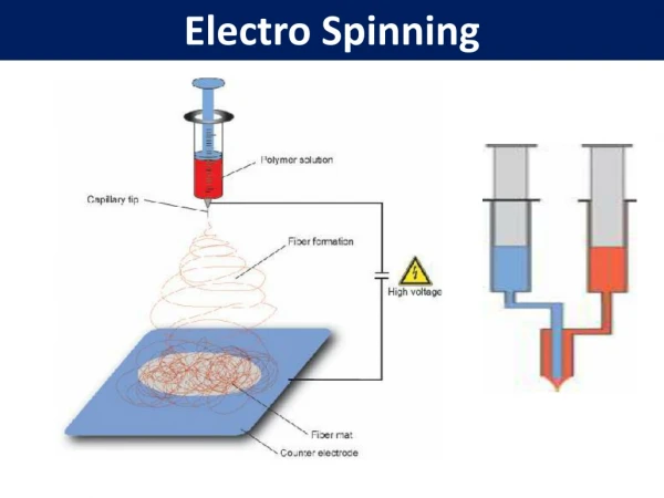
Process Diagram showing fibre formation by electrospinning
How the distribution of charge in the fibre changes as the fibre dries during flight
Parameters 1. Molecular Weight, Molecular-Weight Distribution and Architecture (branched, linear etc.) of the polymer 2. Solution properties (viscosity, conductivity and surface tension) 3. Electric potential, flow rate and concentration 4. Distance between the capillary and collection screen 5. Ambient parameters (temperature, humidity and air velocity in the chamber) 6. Motion of target screen (collector)
Apparatus The standard laboratory setup for electrospinning consists of a spinneret (typically a hypodermic syringe needle) connected to a high-voltage (5 to 50 kV) direct current power supply, a syringe pump, and a grounded collector. A polymer solution, sol-gel, particulate suspension or melt is loaded into the syringe and this liquid is extruded from the needle tip at a constant rate by a syringe pump. Alternatively, the droplet at the tip of the spinneret can be replenished by feeding from a header tank providing a constant feed pressure (figure 3). This constant pressure type feed works better for lower viscosity feedstocks.
A constant pressure laboratory electrospinning machine (set up for horizontal fiber production) Schematic of an electrospinning setup, shown without a syringe pump.
History 1. In the late 16th century William Gilbert set out to describe the behavior of magnetic and electrostatic phenomena. He observed that when a suitably electrically charged piece of amber was brought near a droplet of water it would form a cone shape and small droplets would be ejected from the tip of the cone: this is the first recorded observation of electrospraying. 2. The process of electrospinning was patented by J.F. Cooley in February 1902 (U.S. Patent 692,631) and by W.J. Morton in July 1902 (U.S. Patent 0,705,691. In 1914 John Zeleny, published work on the behavior of fluid droplets at the end of metal capillaries.[4] 3. His effort began the attempt to mathematically model the behavior of fluids under electrostatic forces. Further developments toward commercialization were made by Anton Formhals, and described in a sequence of patents from 1934 (U.S. Patent 1,975,504) to 1944 (U.S. Patent 2,349,950) for the fabrication of textile yarns. Electrospinning from a melt rather than a solution was patented by C.L. Norton in 1936 (U.S. Patent 2,048,651) using an air-blast to assist fiber formation.
History 2. In 1938 N.D. Rozenblum and I.V. Petryanov-Sokolov, working in Prof. N.A. Fuks' group at the Aerosol Laboratory of the L.Ya Karpov Institute in the USSR, generated electrospun fibers , which they developed into filter materials known as " Petryanov filters ". By 1939, this work had led to the establishment of a factory in Tver ' for the manufacture of electrospun smoke filter elements for gas masks. The material, dubbed BF (Battlefield Filter) was spun from cellulose acetate in a solvent mixture of dichloroethane and ethanol. By the 1960s output of spun filtration material was claimed as 20 million m2per annum[ 3. Between 1964 and 1969 Sir Geoffrey Ingram Taylor produced the theoretical underpinning of electrospinning. Taylor’s work contributed to electrospinning by mathematically modeling the shape of the cone formed by the fluid droplet under the effect of an electric field; this characteristic droplet shape is now known as the Taylor cone. He further worked with J. R. Melcher to develop the “leaky dielectric model” for conducting fluids.
History 6. In the early 1990s several research groups (notably that of Reneker and Rutledge who popularised the name electrospinning for the process)demonstrated that many organic polymers could be electrospun into nanofibers. Since then, the number of publications about electrospinning has been increasing exponentially every year. 7. Since 1995 there have been further theoretical developments of the driving mechanisms of the electrospinning process. Reznik et al. describes extensive work on the shape of the Taylor cone and the subsequent ejection of a fluid jet.Work by Hohman et al. investigates the relative growth rates of the numerous proposed instabilities in an electrically forced jet once in flight and endeavors to describe the most important instability to the electrospinning process, the bending (whipping) instability.
Uses The size of an electrospun fiber can be in the nano scale and the fibers may possess nano scale surface texture, leading to different modes of interaction with other materials compared with macroscale materials.n addition to this, the ultra-fine fibers produced by electrospinning are expected to have two main properties, a very high surface to volume ratio, and a relatively defect free structure at the molecular level. This first property makes electrospun material suitable for activities requiring a high degree of physical contact, such as providing sites for chemical reactions, or the capture of small sized particulate material by physical entanglement - filtration. The second property should allow electrospun fibers to approach the theoretical maximum strength of the spun material, opening up the possibility of making high mechanical performance composite materials.
Filtration The use of nanofiber webs as a filtering medium is well established. Due to the small size of the fibers London-Van Der Waals forces are an important method of adhesion between the fibers and the captured materials. Polymeric nanofibers have been used in air filtration applications for more than seven decades.Due to poor bulk mechanical properties of thin nanowebs, they are laid over a filtration medium substrate. The small fiber diameters cause slip flows at fiber surfaces, causing an increase in the interception and inertial impaction efficiencies of these composite filter media. The enhanced filtration efficiency at the same pressure drop is possible with fibers having diameters less than 0.5 micrometer. Since the essential properties of protective clothing are high moisture vapor transport, increased fabric breath-ability, and enhanced toxic chemical resistance, electrospun nanofiber membranes are good candidates for these applications. Lycopodium club moss spores (diameter about 60 micrometers) captured on an electrospun polyvinyl alcohol fiber
Textile manufacturing The majority of early patents for electrospinning were for textile applications, however little woven fabric was actually produced, perhaps due to difficulties in handling the barely visible fibers. However, electrospinning has the potential to produce seamless non-woven garments by integrating advanced manufacturing with fiber electrospinning. This would introduce multi- functionality (flame, chemical, environmental protection) by blending fibers into electrospinlaced (using electrospinning to combine different fibers and coatings to form three dimensional shapes, such as clothing layers in combination with polymer coatings.
Medical 1. Artificial organ components 2. Tissue engineering 3. Implant materials 4. Drug delivery 5. Wound dressing 6. Medical textile materials
Composites Ultra-fine electrospun fibers show clear potential for the manufacture of long fiber composite materials. Application is limited by difficulties in making sufficient quantities of fiber to make substantial large scale articles in a reasonable time scale. For this reason medical applications requiring relatively small amounts of fiber are a popular area of application for electrospun fiber reinforced materials. Electrospinning is being investigated as a source of cost-effective, easy to manufacture wound dressings, medical implants, and scaffolds for the production of artificial human tissues. These scaffolds fulfill a similar purpose as the extracellular matrix in natural tissue. Biodegradable polymers, such as polycaprolactone, are typically used for this purpose. These fibers may then be coated with collagen to promote cell attachment, although collagen has successfully been spun directly into membranes.
Composites SEM picture of the fracture surface of a Polyvinyl alcohol long fiber - epoxy matrix composite - the section thickness is about 12 micrometers Light microscope picture of epoxy resin impregnating an electrospun polyvinyl alcohol reinforcing fiber mat
http://www.textilelab.blogspot.com (Visit My Blog for more Info ) My Facebook Textile related Pages 1. Yarn Manufacturing Technology Link : http://www.facebook.com/pages/Yarn-Manufacturing-Technology/485014954866808 2. Fabric Manufacturing Technology Link : http://www.facebook.com/pages/Fabric-Manufacturing-Technology/459520217425605 3. Garments Manufacturing Technology Link : http://www.facebook.com/pages/Garments-Manufacturing- Technology/472364799463126 3. Wet processing Technology Link : http://www.facebook.com/pages/Wet-Processing-Technology-Dyeing-/468645219825404 4. Fashion-Design-and-Technology Link : http://www.facebook.com/pages/Fashion-Design-and- Technology/587655294583875?ref=ts&fref=ts