Download
1 / 33
340 likes | 493 Vues
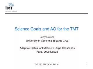
Science Goals and AO for the TMT. Jerry Nelson University of California at Santa Cruz Adaptive Optics for Extremely Large Telescopes Paris, 2009June23. Outline. Project Introduction Telescope overview Science-based metrics TMT key features Major science goals Science Instruments.

E N D
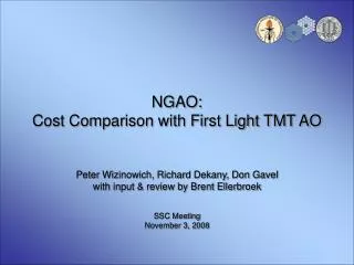
Science Goals and AO for the TMT Jerry Nelson University of California at Santa Cruz Adaptive Optics for Extremely Large Telescopes Paris, 2009June23 TMT.PSC.PRE.09.031.REL01
Outline • Project Introduction • Telescope overview • Science-based metrics • TMT key features • Major science goals • Science Instruments TMT.PSC.PRE.09.031.REL01
Project Introduction • Time line • 2004 project start, design development • 2009 preconstruction phase • 2011 start construction • 2018 complete, first light, start AO science • Partnership • UC • Caltech • Canada • Japan • NSF? • Others? TMT.PSC.PRE.09.031.REL01
Telescope Overview LGSF launch telescope M2 support tripod M2 structural hexapod Tensional members LGSF beam transfer M2 hexagonal ring M2 support columns Elevation journal Nasmyth platform Laser room Azimuth cradle TMT.PSC.PRE.09.031.REL01 M1 cell Azimuth truss
TMT Optical Design:Ritchey Chrétien • M1 Parameters • ø30m, f/1, Hyperboloid • k = -1.000953 • Paraxial RoC = 60.0m • Sag = 1.8m • Asphericity = 29.3mm (entire M1) • M2 Parameters • ø3.1m, ~f/1, Convex hyperboloid, • k = -1.31823 • Paraxial RoC = -6.228m • Sag = ~650mm • Aspheric departure: 850 mm • M3 Parameters • Flat • Elliptical, 2.5 X 3.5m TMT.PSC.PRE.09.031.REL01
Segment Size TMT.PSC.PRE.09.031.REL01
Primary Mirror Control System (M1CS) SSA prototype with dummy segment The M1CS, with the Alignment and Phasing System, turn the 492 individual segments into the equivalent of a monolithic 30 meter diameter mirror. TMT control strategy is an evolutionary improvement on the successful strategy used at the two Keck Telescopes. TMT.PSC.PRE.09.031.REL01 7
M1CS Overview M1CS maintains the overall shape of the primary mirror Attenuates gravity, temperature, wind, and vibration disturbances The primary mirror is aligned and phased using the Alignment and Phasing System (APS) every 4 weeks or after a segment exchange. Look up tables are used in between calibration runs M1CS controls the global shape of the M1 using segment-mounted edge sensors and actuators Real time “On-instrument Wavefront Sensors” (OIWFS) measurements or AO system offloads will augment the static look up tables built using APS data M1 surface error from wind disturbance M1CS off: 223 nm RMS M1CS on: 14 nm RMS TMT.PSC.PRE.09.031.REL01
Science-based Metrics • We use the time needed to make an observation as our metric • Generally assume that we are observing point sources • Generally assume the sources are background limited (most photons come from background, rather than source) • In detail this is based on King’s paper that shows • For these assumptions we get • This is true for seeing-limited or diffraction-limited observations TMT.PSC.PRE.09.031.REL01
Science Merit Function • For seeing-limited observations • PSS ~ D2/image diameter2 • For diffraction-limited observations • image solid angle varies as 1/area, so we get the well known PSS~D4 rule • For finite Strehl, the signal strength is reduced by S, but the background is not reduced, so one gets PSS~S2 where TMT.PSC.PRE.09.031.REL01
Reflectivity, emissivity, throughput • Clearly we want the highest possible reflectivity of our optics • Obvious, since PSS ~ throughput • In the visible r ~ 0.9, so for 3 mirrors, net throughput ~ 0.73 • But, as important, thermal emission from the warm optics can increase the IR background, particularly in K band • When the IR sky is dark (between OH lines) the telescope emission can be the dominant background source • Background ~ (# warm mirrors)*(1-reflectivity) • So it can be VERY important to minimize the number of warm mirrors between the target and the IR instrument TMT.PSC.PRE.09.031.REL01
Thermal backgrounds • Previous graph shows the blackbody flux • Cooling the optic by ~ 30° reduces the flux in this wavelength region by a factor of ~ 15 • Below ~ 2µm the flux is lower than natural backgrounds • These fluxes are multiplied by the mirror emissivities and the number of mirrors • Observatory created backgrounds • Three ambient temperature telescope mirrors (M1, M2, M3) • NFIRAOS science path • 1 ambient window • 5 cold mirrors • 1 cold beam splitter • 1 cold window TMT.PSC.PRE.09.031.REL01
K band thermal background • In the near IR, only K band will see significant thermal flux from telescope • Telescope • 3 mirrors at 1.5% emissivity each • Segment gaps 0.5% • Net background ~ 0.05*ambient blackbody flux • NFIRAOS • Net throughput 85%, so emissivity ~ 0.15 • Cooling 30° reduces flux by a factor of ~ 15, so • Net added background ~ 0.01*ambient blackbody flux TMT.PSC.PRE.09.031.REL01
Field of View • For many science programs larger field of view is useful • Multiple targets • Complex targets (galaxies, etc) • Astrometry where reference objects are needed • Seeing-limited unvignetted 15 arcmin FoV • Atmospheric angular anisoplanatism limits the correctable field of view for AO • One must measure the atmosphere over a sufficient volume to know what the angle dependent correction needs to be • With lasers, one must do tomography to get this information • One must have multiple deformable mirrors to make the added correction TMT.PSC.PRE.09.031.REL01
Impact of multiple deformable mirrors • More DM’s allow greater 3-d fidelity of atmospheric correction, improving correction over larger field of view TMT.PSC.PRE.09.031.REL01
TMT design path • 30m diameter telescope • High reflectivity optics • Only 3 reflections to science instruments or NFIRAOS • NFIRAOS cooled by 30° to reduce thermal emission • NFIRAOS is initial AO system and can feed 3 inst • For AO, two DM’s for increased field of view • For AO, large sky coverage enabled by using 3 partially corrected natural stars (focus, tip, tilt) with 6 LGS • 15 arcmin unvignetted field of view for seeing-limited • All instruments always available in < 10 minutes TMT.PSC.PRE.09.031.REL01
Nasmyth Configuration: First Decade Instrument Suite /IRMS TMT GCAR, April 2009 TMT.PSC.PRE.09.031.REL01 18
NFIRAOS MCAO has better performance than current systems (WIRC) IRMS (NIRES) NFIRAOS IRIS • Dual conjugate AO system • Order 61x61 DM and TTS at h=0 km • Order 75x75 DM at h=12 km • Better Strehl than current AO systems (e.g., Keck ~280-300nm WFE) • Completely integrated system • Fast (<5 min) switch between targets • >50% sky coverage at galactic poles (w/<2mas TT error) TMT.PSC.PRE.09.031.REL01 19
TMT: Key Science • Nature and composition of the Universe • Formation of the first stars and galaxies • Evolution of galaxies and the intergalactic medium • Relationship between black holes and their galaxies • Formation of stars and planets • Nature of extra-solar planets • Presence of life elsewhere in the Universe TMT.PSC.PRE.09.031.REL01 20
Science Drivers for large O/IR Telescopes:3 Basic Types Science that you know you want to do now, but have discovered to be out of reach through experience on 8-10m telescopes. These tend to be what is written in “design reference mission” or “science case” documents Solving problems we do not even know about yet Thinking about “capability space”, or “discovery space”, rather than specific science cases Some intuition is necessary- where will the surprises be, what will we need to follow them up? Supporting roles and “complementarity” with other facilities on ground, in space. Harder to make such roles sound exciting/compelling… BUT next-generation O/IR telescopes will play key role in supporting ALMA, JWST, CCAT, LSST, IXO (CON-X), ZEUS, etc. While many other facilities may not publicly admit that they “need” large O/IR telescopes on the ground (for the same reason), in fact, history suggests that they will. TMT.PSC.PRE.09.031.REL01 21
TMT Detailed Science Case • ~100 page summary of TMT science case (David Silva, editor), completed and posted publicly in October 2007. (http://tmt.org) • Developed with AURA/NOAO as full partner (US community interests accounted for). • Includes science cases developed by instrument feasibility study teams • From fundamental physics and cosmology, to galaxy and structure formation, to extra-solar planets, to solar system studies. TMT.PSC.PRE.09.031.REL01 22
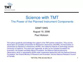
Key TMT features for Science 30m, f/1 primary, RC telescope, ~20’ field 30-m is a judgment about the proper balance between sciencebenefit, cost, technological readiness, and schedule Filled aperture, 492 1.44m segments produces a more concentrated point spread function (PSF), improving signal-to-noise ratios and easing data analysis Integrated AO systems, including Laser Guide Star (LGS) facility MCAO, MOAO, GLAO, MIRAO, ExAO Sensitivity: D4 advantage for background-limited point sources with AO Wavelength range: 0.31 - 28 microns (entire UV-mid-IR) Spatial resolution: 0.007” at 1 micron, 0.014” at 2 microns Instruments on large Nasmyth platforms, addressed by articulated tertiary Rapid switching between targets with different instruments (< 10 min) (Rapid target acquisition: time between targets < 5 min) TMT.PSC.PRE.09.031.REL01 23
SAC Instrument Prioritization Desire to fund first-light instrument suite out of cost-capped construction budget Discovery space: largest gains in broadest range of science in the near-IR (0.8-2.5 microns)@diffraction limit IRIS: IFU+diffraction limited imager IRMS: multiplexed faint object spectroscopy in the near-IR -- leverages investment in facility MCAO system. Ability to perform guaranteed high-priority science we can think of now WFOS PFIvery focused, but very powerful (GPI as a pathfinder...) HROS workhorse capability, strong science case Raw gains in sensitivity (D4) over existing or planned facilities, well defined science MIRES (mid-IR echelle) NIRES (near-IR echelle) WIRC(wider field diff. limited imager) TMT.PSC.PRE.09.031.REL01 24
TMT First Decade Instrument/Capability Suite TMT.PSC.PRE.09.031.REL01 25
TMT Early Light Instrument Suite TMT.PSC.PRE.09.031.REL01 26
TMT Science and “Flow-down” Requirements for early light capabilities have been fine- tuned as a balance between unfettered science-driven desires and technical/fiscal realities (SAC/Project interactions have been crucial). We are proposing to build the most powerful suite of capabilities we can, through close interaction between science and engineering. Currently-envisioned capabilities address a huge range of questions we can formulate now (and complement other powerful facilities) The same capabilities will make new discoveries and will be the primary diagnostic tool for making sense of the discoveries made elsewhere. TMT.PSC.PRE.09.031.REL01 27
IRIS Conceptual Design Team • James Larkin (UCLA), PI, Lenslet IFS • Anna Moore (Caltech), co-I, Slicer IFS • Ryuji Suzuki, Masahiro Konishi, Tomonori Usuda (NAOJ), Imager • Betsy Barton (UC Irvine), Project Scientist • Science Team • Mate Adamkovics(UCB), Aaron Barth(UCI), Josh Bloom(UCB), Pat Cote(HIA), Tim Davidge(HIA), Andrea Ghez(UCLA), Miwa Goto(MPIA), James Graham(UCB), Shri Kulkarni(Caltech), David Law(UCLA), Jessica Lu(UCLA),Hajime Sugai(Kyoto U), Jonathan Tan(UF), Shelley Wright(UCI) • OIWFS (On Instrument Wavefront Sensor) Team (HIA + Caltech) • Led by David Loop, Anna Moore • NSCU (NFIRAOS Science Calibration Unit) Team (U of Toronto) • Led by Dae-Sik Moon TMT.PSC.PRE.09.031.REL01
Motivation for IRIS • Should be the most sensitive astronomical IR spectrograph ever built • Unprecedented ability to investigate objects on small scales. 0.01” @ 5 AU = 36 km (Jovian’s and moons) 5 pc = 0.05 AU (Nearby stars – companions) 100 pc = 1 AU (Nearest star forming regions) 1 kpc = 10 AU (Typical Galactic Objects) 8.5 kpc = 85 AU (Galactic Center or Bulge) 1 Mpc = 0.05 pc (Nearest galaxies) 20 Mpc = 1 pc (Virgo Cluster) z=0.5 = 0.07 kpc (galaxies at solar formation epoch) z=1.0 = 0.09 kpc (disk evolution, drop in SFR) z=2.5 = 0.09 kpc (QSO epoch, Ha in K band) z=5.0 = 0.07 kpc (protogalaxies, QSOs, reionization) M31 Bulge with 0.1” grid (Graham et al.) TMT.PSC.PRE.09.031.REL01 Titan with an overlayed 0.05’’ grid (~300 km) (Macintosh et al.) Keck AO images High redshift galaxy. Pixels are 0.04” scale (0.35 kpc).Barczys et al.)
WFOS/MOBIE Team • Rebecca Bernstein (UCSC), PI • Bruce Bigelow (UCSC), PM • Chuck Steidel (Caltech), PS • Science Team: Bob Abraham(U Toronto), Jarle Brinchmann(Leiden), Judy Cohen(Caltech), Sandy Faber(UCSC), Raja Guhathakurta(UCSC), Jason Kalirai(UCSC), Gerry Lupino(UH), Jason Prochaska(UCSC), Connie Rockosi(UCSC), Alice Shapley(UCLA) • Some “flagship” science cases, “work horse capability” • High quality spectra of faint galaxies/AGN/stars • IGM tomography • Great “follow-up” and “discovery” potential - full wavelength coverage with spectral resolutions up to R = 8000 • JWST, ALMA, etc., follow-up • Sensitivity >14 x current 8m telescopes TMT.PSC.PRE.09.031.REL01
IR Multi-Slit Spectrometer(IRMS) • IRMOS (deployable MOAO IFUs) deemed too risky/expensive for first light • => IRMS: clone of Keck MOSFIRE, first step towards IRMOS • Multi-slit NIR imaging spectro: • 46 slits,W: 160+ mas, L: 2.5” • Deployed behind NFIRAOS • 2’ field • 60mas pixels • EE good (80% in K over 30”) • Spectral resolution up to 5000 • Full Y, J, H, K spectra (one at a time) • Images entire 2’ field Slit width Whole 120” field TMT.PSC.PRE.09.031.REL01
IRMS Spectra Configurable Slit Unit originally developed for JWST (slits formed by opposing bars) Full Y, J, H, K spectra with R ~ 5000 with 160mas (2 pix) slits in central ~1/3 of field TMT.PSC.PRE.09.031.REL01
Summary • TMT will be a 30-m telescope with AO capabilities from the start • ~ 190 nm rms wavefront error over 10 arcsec • First light 2018 • Very large and exciting science case • 8 instruments planned for the first decade • 3 instruments planned for first light • IRIS (an AO NIR integral field spectrograph and imager) • IRMS (an AO NIR multi object spectrometer (46 slits) • WFOS (a seeing-limited multiobject spectrometer with R<8000, and ~ 50 arcmin2coverage) • Many papers will elaborate on TMT AO in this conference TMT.PSC.PRE.09.031.REL01