Download
1 / 23
230 likes | 351 Vues
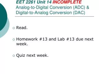
EET 2261 Unit 14 INCOMPLETE Analog-to-Digital Conversion (ADC ) & Digital-to-Analog Conversion (DAC ). Read. Homework #13 and Lab #13 due next week. Quiz next week. Analog Quantities. Most physical quantities (temperature, pressure, light intensity, etc.) are analog quantities.

E N D
EET 2261 Unit 14 INCOMPLETEAnalog-to-Digital Conversion (ADC) & Digital-to-Analog Conversion (DAC) • Read. • Homework #13 and Lab #13 due next week. • Quiz next week.
Analog Quantities • Most physical quantities (temperature, pressure, light intensity, etc.) are analog quantities. • Transducers are devices that convert one of these physical quantities to an analog voltage or current. • Example, a temperature sensor might produce a voltage in mV that is proportional to the temperature in degrees Fahrenheit.
Interfacing to the Analog World • Before a microprocessor can work on analog information, we must first use an analog-to-digital converter (ADC) to transform the analog values into digital binary values. • Conversely, we use a digital-to-analog converter (DAC) to transform digital values from the microprocessor into analog values that can be used to control analog devices. • See Chapter 12 of Floyd’s Digital Electronics for details on ADCs and DACs.
A Typical Application Digital outputs Digital inputs Analog input (voltage or current) Analog output (voltage or current) ADC Micro- processor DAC . . . . . . Control physical variable Transducer Actuator Physical variable
Number of Bits and Accuracy • The ADC periodically samples the analog signal, and converts each sampled value of the analog signal into a binary code. • The more bits that are used in this code, the more accurate is the representation of the original signal. • The following slides (from Floyd’s Chapter 12) show an example of how using 2 bits results in much less accuracy than using 4 bits.
Figure 12.8Light gray = original waveform. Blue = Reconstructed waveform using four quantization levels (2 bits).
Figure 12.10Light gray = original waveform. Blue = Reconstructed waveform using sixteen quantization levels (4 bits).
Resolution • Several common ways of specifying an ADC’s resolution: • Number of bits, n • Number of output codes, = 2n, or number of steps in the output, = 2n − 1 • Percentage resolution, = 1 / (2n − 1), expressed as a percentage • Step size, = Vref / 2n
ADC Hardware • Many analog-to-digital converter chips are available. • Example: the ADC0804 is a popular 8-bit ADC chip. • Our PIC chip has a built-in 10-bit ADC.
The PIC Chip’s Analog Inputs • Seven of the PIC chip’s pins (labeled AN0 through AN7) can be configured as analog inputs to the chip’s internal ADC.
Configuring the Analog Inputs • How do we tell the PIC chip whether we want to use these pins as analog inputs or as digital I/O? • Example: How do we tell it whether we want pin 8 to act as AN5 or as bit 0 of PORT E?
Analog Inputs on the LAB-X1 • On the LAB-X1 board, three of these pins (AN0, AN1, AN3) are permanently connected to the wipers on three potentiometers.
New PICBASIC Commands & Operators in Lab #4 • ADCIN command • PAUSEUS command • / operator • // operator
ADCIN (p. 45 in PICBASIC manual) • Tells the PIC chip to perform an analog-to-digital conversion using its built-in A/D converter, and then saves the result of this conversion. • Example: ADCIN 0 result performs an A/D conversion on the voltage present at analog input 0, and stores the result in the variable named result. • Don’t confuse the ADCIN command with ADCON0 and ADCON1, which are special function registers on the PIC chip.
PAUSEUS(p. 113 in PICBASIC manual) • Recall that the PAUSE command inserts a time delay into your program. This delay is measured in milliseconds. • Example: PAUSE 500 causes a 500 ms delay. • The PAUSEUS command is very similar, but the delay is measured in microseconds instead of milliseconds. • Example: PAUSEUS 500 causes a 500 s delay.
Integer Math • Recall the difference between integers (such as 2 or 47 or 365) and floating-point numbers (such as 3.14 or 1.5 or 16.97). • PICBASIC can only deal with integers, not floating-point numbers. All math operations give integer results. • This requires us to play some tricks if we need to work with floating-point numbers.
Quotient and Remainder • We know that 7÷2 = 3.5 • Recall that another way to say this is that 7÷2 = 3 with a remainder of 1. • In this example, 3 is called the quotient and 1 is called the remainder. • Another example: If you take 20÷8, what is the quotient and what is the remainder?
/ Operator (p. 35 in PICBASIC manual) • The / operator returns the quotient part of a division. • Example: • 7 / 2 in a PICBASIC program will return a result of 3.
// Operator (p. 35 in PICBASIC manual) • The // operator returns the remainder part of a division (sometimes called the modulus). • Example: • 7 // 2 in a PICBASIC program will return a result of 1. • By using both / and //, we can keep track of both the quotient and the remainder part of a division.
Integer Math in Lab #4 • Look at program called A-D Conversion3.pbp • Recall that for a 10-bit A/D conversion using a reference voltage of 5 V, the step voltage is about 4.9 mV. • So to find the voltage (in mV) corresponding to an A/D result, we need to multiply by 4.9. • But since PICBASIC can only handle integers, it can’t handle 4.9. • So instead, we multiply by 49 and then divide by 10.
Integer Math in Lab #4 (Continued) • Now that we have the voltage in mV, we want to print it on the LCD in V. • Example: if the voltage = 2141 mV, then we want to print 2.141 V. • To get the part before the decimal point, take 2141 / 1000. (This returns an answer of 2.) • To get the part after the decimal point, take 2141 // 1000. (This returns an answer of 141.) • Then print those two answers, separated by a decimal point: 2.141.
Another Application • For another use of these integer math tricks, see these documents in the “Documents PIC” folder on the R: shared drive: • “Convert Celsius to Fahrenheit using Integer Math.docx” • “Convert Fahrenheit to Celsius using Integer Math.docx”