Basic Formulae
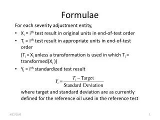
Basic Formulae. CIRCLE. POWER FACTOR. Defination:- Power factor (P.F) is the ratio between active power and apparent power Active power/Apparent power or P.F=Kw/Kva Power factor involves the relationship between two types of power: Working Power and Reactive Power


Basic Formulae
E N D
Presentation Transcript
Basic Formulae CIRCLE
POWER FACTOR • Defination:- • Power factor (P.F) is the ratio between active power and apparent power • Active power/Apparent power or P.F=Kw/Kva • Power factor involves the relationship between two types of power: Working Power and Reactive Power • Most loads in electrical distribution systems are inductive, which means that they require an electromagnetic field to operate • Inductive loads require two kinds of current: • Working Power – performs actual work of creating heat, light, motion, etc • Reactive Power – sustains the electromagnetic field • PF measures how effectively/efficiently electrical power is being used
Examples of Electric Equipment and Their Power Factor Different types of electric equipment have different Power Factors and consequently different efficiencies and current requirements: Name of Equipment Power Factor Percent • Lightly loaded induction motor .20 • Loaded induction motor .80 .30 - .70 • Neon-lighting equipment 1 • Incandescent lamps 1 • All types of resistance heating devices (e.g. toaster, space heater)
Power Triangle Working Power (kW) a Reactive Power (kVAR) b c • Real Power or Working Power (kW) - Measured • Reactive Power (kVAR) - Measured • Apparent Power (kVA) - Calculated Apparent Power (kVA) 2 2 2 Pythagorean Theorem: c = a + b 2 2 2 kVA = kW + kVAR
Active and reactive powers are designated by P & Q respectively. • The average power in a circuit is called active power and the power that supplies stored energy to reactive elements is called reactive power. • P.F For Inductive load:- • Inductive loads cause the current to lag behind the voltage.The wave form of voltage and curret then are “out of phase” with each other. The more out phase they become then the lower the power factor will be.Power factor is usually expressed as cos phi(φ). • Consider a canal boat is being pushd by a horse. • If the horse could walk on water then angle is φ(phi) would be zero and • cos(0)=1.Meaning all the horse power is being used to pull the load. • However the relative position of the horse influnces the power. • As the horse gets closer to barge, angle φ1 increases and power is wasted, but as the horse positioned further away, then angle φ2 gets closer to zero and less power is wasted
ACTIVE POWER (P) • Also known as “real power” or simply “power”. Active power is the rate of producing, transfaring, or using elctrical energy. It is measured in watts and often expressed in kilowatts(KW) or Megawatts(MW). The term “active” or “real” power are used in place of the term “power” alone to differentiate it from “reactive power”.
Or other defination of active power can be that Active power the actual power ( Kw ) or Real power Consumed by a load .If we are not maintaining the power factor at the appreciable value that is if cos0 is decreasing then sino is increased that is VI SIN o that is reactive power. • cos o = Active power / Apparent Power = Kw / KVA. • Reactive power = VI SINo = Kvar. • The power which is actually utilised in the circuit is known as active power. • REACTIVE POWER (Q) • Reactive power is nothing but which is delivered by the inductive load and does not do any usefulwork . It is measured in Kvar or simply Var. • Reactive power is that component of power for which we don't pay any money, but we put our own system to a pressure. It is like somebody climbing upstairs and coming down without doing anything
APPARENT POWER (S) • The product of the voltage (in volts) and the current (in amperes). It comprises both active and reactive power.. • It is measured in “volt-amperes”(va) and often expressed in “kilovolt-amperes”(kva) or “Megavolt-amperes”(Mva). When current and voltage wave forms are in phase as shown below then corresponding power wave form of an electrical network would be:-
When current and voltage wave forms are out of phase as shown below then corresponding power wave form of an electrical network would be:-
Causes Of Low Power Factor • A poor power factor can be the result of either a significant phase difference between the voltage and current at the load terminals or it can be due to a high harmonic content or distorted/discontineous current wave form. Poor load current phase angle is generally the result of an inductive load such as an induction motor , power transformere, lightening ballasts, welder or induction furnanc, Induction generators, wind mill generators and high intensity discharge lights. • Dis-Advangates Of a Low Power Factor • Increases heating losses in transformer and distribution equipments. • Reduce plant life. • Unstablise voltage levels. • Increase power losses. • Upgrade needs costly equipments. • Decreases energy efficiency. • Increases electricity cost by paying power factor surcharges.
Correction Of Power Factor • Most loads on an electrical distribution system fall into one of three catogries; resistive, inductive or capactive. World wide the most common is likely to be inductive (almost 85%). Typical examples of this includes transformers, fluorescent lightening and AC induction motors. • Most inductive loads use a conductive coil winding to produce an electromagnetic field, allowing the motor to function. • All inductive loads require two kind o f power to operate: • Active Power:- (KW)- to produce the motive force • Reactive Power:- (KVAR)- to energize the magnetic field • The operating power from the distribution system is composed of both active (working) and reactive (non-working) elements. The active power does useful work in driving the motor whereas the reactive power only provides the megnetic field
The amount of power capacitor KVAR required to correct a system to a desired power factor level, is the difference between the amount of KVAR in the uncorrected system and the amount of desired KVAR in the corrected system • The most efficient location for power factor capacitor is at the load. Capacitors work from the point of installation back to the generating source. Individual motor correction is not always practical, sometimes it is more practical to connect larger capacitors on the distribution bus or install an automatic syatem at the incoming service along with fixed capacitors at the load
KVAR Correction • Capactive Powet Factor Correction (PFC) is applied to electric circuits as a means of minimising the inductive componenet of the current and there by reducing the losses in the supply. The introduction of power factor correction capactiors is a widely recognised method of reducing an electrical load, thus minimising wasted energy and hence improving the efficiency of a plant and reducing the electricity bill. • It is not usually necessary to reach unity, i.e. Power factor 1, since most supply companies are happy with a PF of 095 to 0.98. • By installing suitably sized switched capacitors into the circuit, the the power factor is improved and the value becomes nearer to 1 thus minimising wasted energy and improving the efficiency of a plant. • Power factor can be increased by synchronous motor as well.
Advantages Of Power Factor Correction • Eliminate power factor penalities • Increase system capacity • Reduce line losses in distribution systems • Conserve energy • Improve voltage stability • Increase equipment life • Save on utility cost • Enhance equipment operation by improving voltage • Improve energy efficiency • Reduction in size of transformers, cables and switchgear in new installations • Delay costly upgrades • Less total plant KVA for the same KW working power • Improves voltage regulation due to reduced line voltage drop