AVR Microcontroller
Embedded System Designing. AVR Microcontroller. Introduced by: Eng. Abd-Elsalam Boda_eng@hotmail.com. Course Outline. Introduction. AVR microcontroller Architecture. C Review. Memories in AVR. I/O Ports. Interrupts, “External Interrupts”. Timers/Counters

AVR Microcontroller
E N D
Presentation Transcript
Embedded System Designing AVR Microcontroller Introduced by: Eng. Abd-Elsalam Boda_eng@hotmail.com
Course Outline • Introduction. • AVR microcontroller Architecture. • C Review. • Memories in AVR. • I/O Ports. • Interrupts, “External Interrupts”. • Timers/Counters • Timer/counter 0 … 8 bit timer/counter. • Timer/counter 1 … 16 bit timer/counter. • Timer/counter 2 … 8 bit timer/counter. • Analog comparator “AC”. • Analog to digital converter “A/D”. • Serial peripheral interface “SPI”. • USART. • Two wire serial interface “I2C”. • Applications “According to the course flow”.
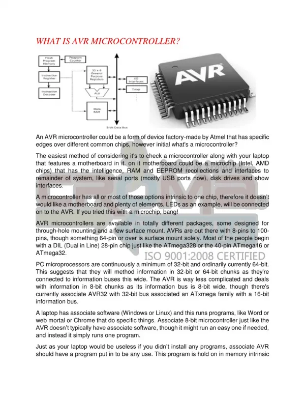
Introduction • Microprocessor vs. Microcontroller RAM ROM Microcontroller Serial & Parallel Ports Micro- Processor I/O Port Timer Interrupt
Introduction • Microprocessor: • Faster. • General purpose. • Expensive • CPU is stand-alone, RAM, ROM, I/O, timer are separate. • Designer can control the amount of ROM, RAM and I/O ports. • It is cheaper compared to the microcontroller with the same features.
Introduction • Microcontroller: • Slower. • Stand alone operation. • Cheaper. • CPU, RAM, ROM, I/O and timer are all on a single chip(but fixed amount). • for applications in which cost, power and space are critical. • Single Operation.
Introduction • Memory types: • There are several types of memory which is divided into RAM (Volatile ) and ROM and Flash memory (Non-Volatile) and each type is divided into sub types as follows: • RAM(Random Access Memory): • SRAM(Static RAM): • Very expensive • Very high performance • Constructed of Flip-Flops
Introduction • RAM(Random Access Memory): • DRAM(Dynamic RAM): • Cheap • Constructed from Capacitors so it needs to be refreshed periodically. • It is divided into: • SDRAM(Synchronous DRAM) • SDR-SDRAM(Single Data Rate) • DDR-SDRAM(Double Data Rate) • DDR-SDRAM has better performance and faster than the SDR-SDRAM and it is commonly used now in our computer
Introduction • RAM(Random Access Memory): • DRAM(Dynamic RAM): • Cheap • Constructed from Capacitors so it needs to be refreshed periodically. • It is divided into: • SDRAM(Synchronous DRAM) • SDR-SDRAM(Single Data Rate) • DDR-SDRAM(Double Data Rate) • DDR-SDRAM has better performance and faster than the SDR-SDRAM and it is commonly used now in our computer
Introduction • ROM(Read Only Memory): • ROM(ROM) • PROM(Programmable ROM). • EPROM (Erasable PROM). • EEPROM(Electrically Erasable PROM).
Introduction • Flash Memory: • It is non-volatile computer memory that can be electrically erased and reprogrammed. It is a technology that is primarily used in memory cards and USB flash drives for general storage and transfer of data between computers and other digital products. It is a specific type of EEPROM (Electrically Erasable Programmable Read-Only Memory) that is erased and programmed in large blocks
Introduction • LEDS and Switches: • LED(Light Emitting Diode): • A light-emitting diode (LED) is a semiconductor diode that emits light when an electrical current is applied in the forward direction of the device, as in the simple LED circuit.
Introduction • Switches. • Switches type: • Toggle switch. • Pushbutton switch. • DIP switch.
Introduction • Switches • The shown circuit is a sample switch active low circuit, when we press on the pushbutton the ATMEL pin will be connected to the ground, otherwise it will be connected to the VCC
Introduction • Opto-isolators and Opto-couplers • The Opto-coupler consists of the control part which is the photo-diode and the load part which is the photo-transistor. • When the voltage is applied on the photo-diode, it emits light which turns the photo-transistor on (be in the saturation mode “short circuit”). • It is very fast • The Switch ON/OFF speed • is up to120 MHz with high • Performance Opto-Coupler.
Introduction • Relays • All Relays Operate Using the same principle. • Consisted of a control circuit • has a coil “in the green color” and a load circuit that has a switch “ in the red color”.
Introduction • Buffers: • Buffers are used to protect IC’s from high current because it passes voltage and holds current • Also data buffer is a region of memory used to temporarily hold data while it is being moved from one place to another. • Buffers IC’s like 74244, 74245.
ATmega16 Features • From the data Sheet.
C Review: • Include Files: “according to Codevision” • AVR header files e.g. mega8535, mega16, 902313, tiny22,…ect. • C header files e.g. math.h, string.h, stdlib.h, stdio.h,...ect. • Other useful header files e.g. Delay.h, lcd.h, spi.h, I2C.h, Gray.h,…ect.
C Review: • C functions • C main function must be endless. • Other function could be used. • Function prototype declaration. Return-type function-name(Arguments or “the inputs”); • Function itself. Return-type function-name(Arguments or “the inputs”) { }
C Review: • Variable Declaration: Type Size (Bits) Range bit 1 0 , 1 char 8 -128 to 127 unsigned char 8 0 to 255 signed char 8 -128 to 127 int 16 -32768 to 32767 short int 16 -32768 to 32767 unsigned int 16 0 to 65535 signed int 16 -32768 to 32767
C Review: • Variable Declaration: Type Size (Bits) Range long int 32 -2147483648 to 2147483647 unsigned long int 32 0 to 4294967295 signed long int 32 -2147483648 to 2147483647 float 32 ±1.175e-38 to ±3.402e38 double 32 ±1.175e-38 to ±3.402e38
C Review: • Variable Declaration: Type Size (Bits) Range long int 32 -2147483648 to 2147483647 unsigned long int 32 0 to 4294967295 signed long int 32 -2147483648 to 2147483647 float 32 ±1.175e-38 to ±3.402e38 double 32 ±1.175e-38 to ±3.402e38
C Review: • Operators: • Assignment operator (x=y) … (+=, -=, /=, *=) • Increment/decrement operator ++/-- • Equal operator (==) • Less than (<) … less than or equal (<=) • Greater than (>) … less than or equal (>=) • Not equal (!=) • Logical operators: • And (&&) Bitwise AND (&) • Or (||) Bitwise OR(|) • Not (!) Bitwise XOR(^) • Complement (~) • Right shifted (>>) … Left shifted (<<)
C Review: • If Statement: If(condition is true) { Do whatever here… } Else if (another condition is true) { Do whatever here… } : . Else { Do a default operation } If there are no braces the next statement is the only statement under the condition
C Review: • The For statement For(initial; condition ; increment) { Do whatever here… } for (count = 100; count > 0; count--) for (count = 0; count < 1000; count += 5) count = 1; for (x=5 ; count < 1000; count++) for (count = 0; count < 100; ) {count++;} for (i = 0, j = 999; i < 1000; i++, j--) b[j] = a[i]; If there are no braces the next statement is the only statement under the for statement
C Review: • While statement While(condition) { Do whatever here… } Do { }while(condition);
C Review: • Arrays: • Char arr1[5]; • Char arr2[]=“legend”; • Char arr1[5]={1,2,3,4,5}; • Arr1[5] … from arr1[0] to arr1[4] • Indexed by integer. • Tow dimensional array x[4][3]; • Pointers • Char *x; char *x=“legend”; • x++; *x++; • Char x; &x++; x++;
ATmega16 • Pin description: • 4 ports A,B,C,D each has 8 pins. • RESET input. A low level on this pin for longer than the minimum pulse length will generate a reset. • XTAL1 Input to the inverting Oscillator amplifier and input to the internal clock operating circuit. • XTAL2 Output from the inverting Oscillator amplifier. • AVCC is the supply voltage pin for Port A and the A/D Converter. It should be externally connected to VCC. • AREF is the analog reference pin for the A/D Converter.
ATmega16 • Status Register • Bit 7 – I: Global Interrupt Enable The Global Interrupt Enable bit must be set for the interrupts to be enabled. The individual interrupt enable control is then performed in separate control registers. The I-bit is cleared by hardware after an interrupt has occurred, and is set by the RETI instruction to enable subsequent interrupts. The I-bit can also be set and cleared by the application with the SEI and CLI instructions. #asm(‘’sei”); #asm(“cli”);
ATmega16 • Status Register • Bit 6 – T: Bit Copy Storage • Bit 5 – H: Half Carry Flag • Bit 4 – S: Sign Bit, S = N ^V • Bit 3 – V: Two’s Complement Overflow Flag • Bit 2 – N: Negative Flag • Bit 1 – Z: Zero Flag • Bit 1 – Z: Zero Flag
ATmega16 • Stack Pointer The Stack is mainly used for storing temporary data, for storing local variables and for storing return addresses after interrupts and subroutine calls. The AVR Stack Pointer is implemented as two 8-bit registers.
ATmega16 Memories • In-System Reprogrammable Flash Program Memory • The ATmega16 contains 16K bytes On-chip In-System Reprogrammable Flash memory for program storage. • The Flash is organized as 8K x 16. • The Flash memory has an endurance of at least 10,000 write/erase cycles. The ATmega16 Program Counter (PC) is 13 bits wide.
ATmega16 Memories • SRAM Data Memory • 1120 Data Memory locations address the Register File, the I/O Memory, and the internal data SRAM. The first 96 locations address the Register File and I/O Memory, and the next 1024 locations address the internal data SRAM.
ATmega16 Memories • EEPROM Data Memory • The ATmega16 contains 512 bytes of data EEPROM memory. It is organized as a separate data space, in which single bytes can be read and written. The EEPROM has an endurance of at least 100,000 write/erase cycles. • EEPROM Read/Write Access There are a several registers we will deal with: • The EEPROM Address Register – EEARH and EEARL. • The EEPROM Data Register – EEDR. • The EEPROM Control Register – EECR.
ATmega16 Memories • The EEPROM Address Register – EEARH and EEARL. • EEPROM Data Register – EEDR.
ATmega16 Memories • The EEPROM Control Register – EECR. • Bit 3 – EERIE: EEPROM Ready Interrupt Enable Writing EERIE to one enables the EEPROM Ready Interrupt if the I-bit in SREG is set. Writing EERIE to zero disables the interrupt. The EEPROM Ready interrupt generates a constant interrupt when EEWE is cleared.
ATmega16 Memories • The EEPROM Control Register – EECR. • Bit 2 – EEMWE: EEPROM Master Write Enable The EEMWE bit determines whether setting EEWE to one cause the EEPROM to be written. When EEMWE is set, setting EEWE within four clock cycles will write data to the EEPROM at the selected address If EEMWE is zero, setting EEWE will have no effect. When EEMWE has been written to one by software, hardware clears the bit to zero after four clock cycles. See the description of the EEWE bit for an EEPROM write procedure.
ATmega16 Memories • The EEPROM Control Register – EECR. • Bit 1 – EEWE: EEPROM Write Enable. The EEPROM Write Enable Signal EEWE is the write strobe to the EEPROM. When address and data are correctly set up, the EEWE bit must be written to one to write the value into the EEPROM. The EEMWE bit must be written to one before a logical one is written to EEWE, otherwise no EEPROM write takes place.
ATmega16 Memories • The following procedure should be followed when writing the EEPROM (the order of steps 3 and 4 is not essential): • Wait until EEWE becomes zero. • Wait until SPMEN in SPMCR becomes zero. • Write new EEPROM address to EEAR (optional). • Write new EEPROM data to EEDR (optional). • Write a logical one to the EEMWE bit while writing a zero to EEWE in EECR. • Within four clock cycles after setting EEMWE, write a logical one to EEWE.
ATmega16 Memories • Cautions: • An interrupt between step 5 and step 6 will make the write cycle fail, since theEEPROM Master Write Enable will time-out. • If an interrupt routine accessing theEEPROM is interrupting another EEPROM access, the EEAR or EEDR Register will be modified, causing the interrupted EEPROM access to fail. It is recommended to have the Global Interrupt Flag cleared during all the steps to avoid these problems.
ATmega16 Memories • Cautions: • When the write access time has elapsed, the EEWE bit is cleared by hardware. The user software can poll this bit and wait for a zero before writing the next byte. • WhenEEWE has been set; the CPU is halted for two cycles before the next instruction is executed.
ATmega16 Memories • The EEPROM Control Register – EECR. • Bit 0 – EERE: EEPROM Read Enable The EEPROM Read Enable Signal EERE is the read strobe to the EEPROM. When the correct address is set up in the EEAR Register, the EERE bit must be written to a logic one to trigger the EEPROM read. The EEPROM read access takes one instruction, and the requested data is available immediately.
ATmega16 Memories • Cautions: • When the EEPROM is read, the CPU is halted for four cycles before the next instruction is executed. • The user should poll the EEWE bit before starting the read operation. • If a write operation is in progress, it is neither possible to read the EEPROM, nor to change the EEAR Register.
ATmega16 Memories void EEPROM_write(unsigned int uiAddress, unsigned char ucData) { /* Wait for completion of previous write */ while(EECR & (1<<EEWE)); /* Set up Address and Data Registers */ EEAR = uiAddress; EEDR = ucData; /* Write logical one to EEMWE */ EECR |= (1<<EEMWE); /* Start eeprom write by setting EEWE */ EECR |= (1<<EEWE); }
ATmega16 Memories unsigned char EEPROM_read(unsigned int uiAddress) { /* Wait for completion of previous write */ while(EECR & (1<<EEWE)); /* Set up Address Register */ EEAR = uiAddress; /* Start eeprom read by writing EERE */ EECR |= (1<<EERE); /* Return data from Data Register */ return EEDR; }
ATmega16 I/O Ports • Three I/O memory address locations are allocated for each port, one each for the Data Register, Data Direction Register, and the Port Input Pins. • The Port Input Pins I/O location is read only, while the Data Register and the Data Direction Register are read/write. • The DDxn bit in the DDRx Register selects the direction of this pin. If DDxn is written logic one, Pxn is configured as an output pin. If DDxn is written logic zero, Pxn is configured as an input pin.
ATmega16 I/O Ports • If PORTxn is written a logic one when the pin is configured as an input pin, the pull-up resistor is activated. To switch the pull-up resistor off, PORTxn has to be written logic zero or the pin has to be configured as an output pin. • If PORTxn is written a logic one when the pin is configured as an output pin, the port pin is driven high. If PORTxn is written a logic zero when the pin is configured as an output pin, the port pin is driven low. • Reading the Pin Value: Independent of the setting of Data Direction bit DDxn, the port pin can be read through the PINxn Register bit.
ATmega16 I/O Ports • Register Description for I/O-Ports: • Port A Data Register – PORTA • Port A Data Direction Register - DDRA • Port A Input Pins Address – PINA