Download
1 / 13
130 likes | 148 Vues
This biomedical engineering device measures the degree of re-innervation and muscle fiber reconstruction in patients with laryngeal muscle paralysis, improving their quality of life.

E N D
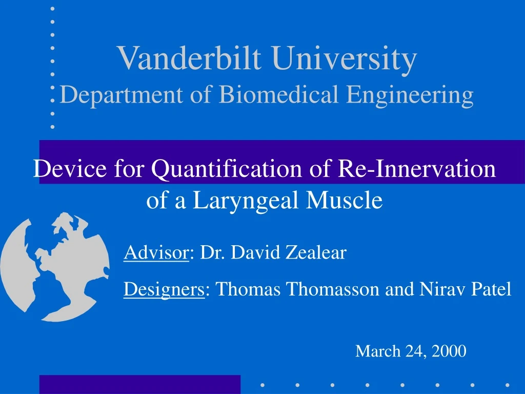
Vanderbilt UniversityDepartment of Biomedical Engineering Device for Quantification of Re-Innervation of a Laryngeal Muscle Advisor: Dr. David Zealear Designers: Thomas Thomasson and Nirav Patel March 24, 2000
Background • What ?- Development of a design and technique for the quantitative measurement of a re-innervated laryngeal muscle • Why ?- To increase quality of life for patients suffering from denervated muscular system • From? -Surgical removal of cancer growth, nerve damage, arytenoidectomy, vocal fold resection.1 • Who ? - Patients that have lost muscle control through paralysis of laryngeal muscles (2estimates of 16,000/yr in U.S., 25% having bilateral paralysis) • 1. Michaels, Pathology of the Larynx., 1984 2. National Center for Health Statistics, 1996.
Background Cont... • How ?- Recording EMG readings passes through the developed circuitry while tactile stimulation of the nerves is performed • Analysis? -Integrated recordings over time show degree of re-innervation and muscle fiber reconstruction counts • Synkinetic Ratio- Level of Re-innervation over initial nerve signals
Background Cont... • Electrical stimulus must be performed before 7 months after denervation of laryngeal muscle--fibrosis.3 • Stimulus paradigm-- 1 second pulse train with 2msec pulses at 30 Hz with a current of 4-14mA.4 • Neuromuscular block, Botox, suppresses adductor movement allowing greater abductor movement (7mm dynamic opening)5 3,4,5 - Zealear, Billante. Emerging Approaches to Laryngeal Rehabilitation
Objectives • To Measure electromyographical potentials using electrodes. • To establish an index of synkinesis that compares pathological nerve re-innervation to normal nerve alignment • To use index of synkinesis to determine severity of pathology. • To measure muscle fiber bundles that have been re-innervated (secondary measurement of paralysis severity)
Circuit • High Pass Filter • Removes DC noise and low frequency AC noise • Low Pass Filter • Cutoff frequency of 100K Hz • Rectifier • Returns absolute value of input • Positive Wave Rectifier: Vout = Vin • Diodes Act Linearly in Feedback Loop
Circuit Cont... • Integrator • Calculates area under input curve • Integrates the Rectified Wave Over Time by the equation: Vout = -1/(Rf Cf ) Vin dt • Peak Detector • Holds maximum value from the integrator
Circuit Output Input Signal Rectified Signal Integrated Signal/ Peak Value
EMG Signals From Dog Subjects Signal From Indirect Stimulation of Nerve Signal From Direct Stimulation of Nerve
Design Implementations • Researched and Designed Circuit for optimal performance • Circuit Components selected based on effectiveness and cost efficiency • voltage limitations for powering op amp • minimize DC noise within op amps • Potentiometer added in Circuit Design for Calibration that will be performed with a 2Vp-p 1kHz sine wave
DesignSafe Analysis • Circuit Components Shorting • Design Around Hazard While Hard Wiring • Overloading Circuit • Add Neon Bulb between input Electrodes • Direct/Indirect Contact With Live Wires • Design Around By Properly Insulating Circuit and Components
Begin Hard Wiring Circuit onto a Vector Board Debug the Vector Board Add a digital output meter, which has been ordered, to the circuit to serve as a final output source Current Work
Future Work • Use circuit during canine experiments • Development of index of synkinesis through statistical analysis upon completion of canine experiments • Begin Poster presentation design