Evaluation and Recommendations for Silicon Tracking in ILD
590 likes | 725 Vues
This document presents an overview of the requirements and current situation regarding silicon tracking in the International Linear Collider's ILD detector. Key aspects include the necessity for good momentum resolution, impact parameter precision, and angular acceptance, particularly in forward tracking as collider energies increase. It also discusses complexities in the tracking system, such as varying detector resolutions and material budget implications. Insights from collaborators shed light on efficient configuration for improved tracking quality and calibration, emphasizing the role of timing resolution in track identification.

Evaluation and Recommendations for Silicon Tracking in ILD
E N D
Presentation Transcript
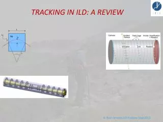
TRACKING IN ILD: A REVIEW A. Ruiz-Jimeno,ILD-Krakow-Sept2013
Outline • REQUIREMENTS • CURRENT SITUATION • HOW TO PROCEED (mainly silicon tracking) Thanksfortheir inputs toD.Moya, R. D. Settles, Y. Sugimoto, I. Vila and M. Vos A. Ruiz-Jimeno,ILD-Krakow-Sept2013
Requirements Good momentum resolution A. Ruiz-Jimeno,ILD-Krakow-Sept2013
Requirements Good momentum resolution Good impact parameter precision b,c,ttagging barrel A. Ruiz-Jimeno,ILD-Krakow-Sept2013
Requirements Good momentum resolution Good impact parameter precision b,c,ttagging barrel Good pattern recognition Full angular acceptance High jet multiplicity A. Ruiz-Jimeno,ILD-Krakow-Sept2013
Full angular acceptance Forward tracking increasingly important with higher c.m.s. energy 2009 JINST4 P08002 A. Ruiz-Jimeno,ILD-Krakow-Sept2013
Full angular acceptance Forward tracking increasingly important with higher c.m.s. energy 2009 JINST4 P08002 A. Ruiz-Jimeno,ILD-Krakow-Sept2013
Good momentum resolution Goal ILD Gluckstern formula for N equally spaced layers (N>10, no Multiple Scattering) Lever arm L perpendicular to magnetic field B Degradation at small angle due to the reduction of L TPC resolution is dependent of drift length ILD 100GeV muons (dashed line: simulation; contonuousline:Gluckstern) Note also that D(1/p)~D(1/pt) * sinq A. Ruiz-Jimeno,ILD-Krakow-Sept2013
Good momentum resolution Real layout ILD inner part (ideal) • Complex tracking system: • - srf not uniform • - at angles<40º, N decreases, added to shorter L • - forward tracking, N<10, srf~7mm Multiple scattering contribution depends on the material budget. Equals the other term at p~50GeV, at large angle A. Ruiz-Jimeno,ILD-Krakow-Sept2013
Good momentum resolution Real layout ILD inner part (ideal) • Complex tracking system: • - srf not uniform • - at angles<40º, N decreases, added to shorter L • - forward tracking, N<10, srf~7mm Multiple scattering contribution depends on the material budget. Equals the other term at p~50GeV, at large angle A. Ruiz-Jimeno,ILD-Krakow-Sept2013
Tracking • First question to be carefully analysed A. Ruiz-Jimeno,ILD-Krakow-Sept2013
Tracking • First question to be carefully analysed SET, ETD provide precise space points, added to TPC points. ETD resolution degraded by TPC end plate SET, ETD improve matching efficiency TPC-ECAL SET, ETD add material budget in front of ECAL SET provides time stamping (also SIT) SET, ETD cost is ten times the cost of inner tracking A. Ruiz-Jimeno,ILD-Krakow-Sept2013
Tracking • First question to be carefully analysed SET, ETD provide precise space points, added to TPC points. ETD resolution degraded by TPC end plate SET, ETD improve matching efficiency TPC-ECAL SET, ETD add material budget in front of ECAL SET provides time stamping (also SIT) SET, ETD cost is ten times the cost of inner tracking To answer the question it is needed to analyze it with a realistic ILD layout. Calorimeter people input is very important A. Ruiz-Jimeno,ILD-Krakow-Sept2013
Tracking • SIT, TPC, SET • There are two important quality functions for the tracking using this configuration: • REDUNDANCY • INTERNAL CALIBRATION • Unfortunately, these are difficult to quantify, and thus difficult to optimize. The good timing resolution of the silicon detectors relative to the time between bunches in the ILC together with the high spatial precision helps in time-stamping tracks and assigning them to a given bunch within an ILC bunch train. • The time-stamping in ILD is found to be precise to ~ 2 ns (to be compared to ~ 300 ns between BXs at the ILC) so that the bunch crossing which produced the track (the T0) can be uniquely identified.
Good impact parameter precision Goal ILD Forward- backward - The distance to the interaction point (IP) of the innermost hit goes as (sin-1q, cos-1q) in the (barrel, forward) tracking - Multiple scattering is proportional to square root of material thickness in X0 - Finally, b is multiplied, in the forward tracker, by the ratio of the IP distance along z (L) of the first disk to the inner radius of the barrel tracker (R) barrel A. Ruiz-Jimeno,ILD-Krakow-Sept2013
Good impact parameter precision Goal ILD Forward- backward - The distance to the interaction point (IP) of the innermost hit goes as (sin-1q, cos-1q) in the (barrel, forward) tracking - Multiple scattering is proportional to square root of material thickness in X0 - Finally, b is multiplied, in the forward tracker, by the ratio of the IP distance along z (L) of the first disk to the inner radius of the barrel tracker (R) barrel Limited by the background near IP The gap between barrel and end cap limited by mechanics and services A. Ruiz-Jimeno,ILD-Krakow-Sept2013
Vertex detector in DBD Performance goal achieved in barrel A. Ruiz-Jimeno,ILD-Krakow-Sept2013
Questions related to the vertex detector optimization • Q1. Is the outer radius of 60 mm optimal? • The fact that changing the pixel size of outer layers from 5um to 10um does not affect the impact parameter resolution suggests that the outer trackers (SIT and TPC) are working as the “outer layer” of the vertexing system. That implies the outer radius of the VTX could be reduced without degrading the impact parameter resolution. A. Ruiz-Jimeno,ILD-Krakow-Sept2013
Questions related to the vertex detector optimization • Q1. Is the outer radius of 60 mm optimal? • The fact that changing the pixel size of outer layers from 5um to 10um does not affect the impact parameter resolution suggests that the outer trackers (SIT and TPC) are working as the “outer layer” of the vertexing system. That implies the outer radius of the VTX could be reduced without degrading the impact parameter resolution. • Q2. What is the impact of the performance of outer trackers (SIT and TPC) on the impact parameter resolution? • If the outer trackers are really working as the “outer layer” of the vertexing system, performance (spatial resolution) of the outer trackers must have impact on the impact parameter resolution. A. Ruiz-Jimeno,ILD-Krakow-Sept2013
Questions related to the vertex detector optimization • Q1. Is the outer radius of 60 mm optimal? • The fact that changing the pixel size of outer layers from 5um to 10um does not affect the impact parameter resolution suggests that the outer trackers (SIT and TPC) are working as the “outer layer” of the vertexing system. That implies the outer radius of the VTX could be reduced without degrading the impact parameter resolution. • Q2. What is the impact of the performance of outer trackers (SIT and TPC) on the impact parameter resolution? • If the outer trackers are really working as the “outer layer” of the vertexing system, performance (spatial resolution) of the outer trackers must have impact on the impact parameter resolution. • Q3. What is the impact of spatial resolution and material budget of the vertex detector on the physics performance? • It is clear that better spatial resolution and less material budget of the VTX (inner layers) gives better impact parameter resolution. However, it has not been demonstrated well how much the better IP resolution improves physics output. Physics potential as a function of these parameters should be demonstrated. Effect of the material budget of the end plate, support shell, cryostat, and cables should be studied combined with the outer trackers. (see later…) A. Ruiz-Jimeno,ILD-Krakow-Sept2013
Good impact parameter precision Functional form, toy detector with 0,12% X0 per layer, 3 m spatial resolution in rfand z 1 GeV 100 GeV JINST 8 T06001 2013 Realistic material budget can degrade notoriously the impact parameter resolution Mainly vertex cables, services… (not FTD) A. Ruiz-Jimeno,ILD-Krakow-Sept2013
Engineering challenges: Beam pipe as thin as possible Careful optimization of the services and support structures of the barrel vertex detector to avoid a.m.a.p. the line of sight between the IP and the innermost disk Routing of the barrel vertex detector cables and services over the end-cap A. Ruiz-Jimeno,ILD-Krakow-Sept2013
Good pattern recognition OCCUPANCY FTD1 (eett) peak FTD1 (eett) average Pixels of 25*25 mm2 in the most inner region allows robust pattern recognition for a readout time of 50 msec ( about 100 BX) JINST 8 T06001 2013 A. Ruiz-Jimeno,ILD-Krakow-Sept2013
Good pattern recognition Microstrip detectors in the forward tracker have radially oriented strips. To constraint the second coordinate with a low proportion of ghost hits, an stereo angle a of about 100 mrad will be used 100*100 mm2 sensors with 25 mm pitch a= 100 mrad s(r) = 20 s(space point resolution of the detector) Moderately precise r-measurements should be needed in all the forward tracking layers to have a robust pattern recognition JINST 8 T06001 2013 A. Ruiz-Jimeno,ILD-Krakow-Sept2013
More questions related to the vertex ( and tracker) detector optimization • Q4. What is the minimum momentum to be reconstructed with high efficiency from the viewpoint of physics? A. Ruiz-Jimeno,ILD-Krakow-Sept2013
More questions related to the vertex ( and tracker) detector optimization • Q4. What is the minimum momentum to be reconstructed with high efficiency from the viewpoint of physics? • Q5. How much do the pair background hits degrade the tracking efficiency? • The field map has to be optimized when we study the background. A. Ruiz-Jimeno,ILD-Krakow-Sept2013
More questions related to the vertex ( and tracker) detector optimization • Q4. What is the minimum momentum to be reconstructed with high efficiency from the viewpoint of physics? • Q5. How much do the pair background hits degrade the tracking efficiency? • The field map has to be optimized when we study the background. • Q6. Is the current configuration of the vertex detector optimized for 250GeV run? • At 250GeV, beam background shape could be different from 500GeV, and the VTX/beam pipe configuration could also be different from the design for 500GeV/1TeV. A. Ruiz-Jimeno,ILD-Krakow-Sept2013
More questions related to the vertex ( and tracker) detector optimization • Q4. What is the minimum momentum to be reconstructed with high efficiency from the viewpoint of physics? • Q5. How much do the pair background hits degrade the tracking efficiency? • The field map has to be optimized when we study the background. • Q6. Is the current configuration of the vertex detector optimized for 250GeV run? • At 250GeV, beam background shape could be different from 500GeV, and the VTX/beam pipe configuration could also be different from the design for 500GeV/1TeV. • Q7. What is the data acquisition (data flow) strategy with large beam background hits? • The data size of the VTX is huge. The strategy of handling these large amount of data should be clarified. A. Ruiz-Jimeno,ILD-Krakow-Sept2013
More questions related to the vertex ( and tracker) detector optimization • Q4. What is the minimum momentum to be reconstructed with high efficiency from the viewpoint of physics? • Q5. How much do the pair background hits degrade the tracking efficiency? • The field map has to be optimized when we study the background. • Q6. Is the current configuration of the vertex detector optimized for 250GeV run? • At 250GeV, beam background shape could be different from 500GeV, and the VTX/beam pipe configuration could also be different from the design for 500GeV/1TeV. • Q7. What is the data acquisition (data flow) strategy with large beam background hits? • The data size of the VTX is huge. The strategy of handling these large amount of data should be clarified. Doesthe ILD designproviderobust tracking downto 6 degrees? The CLIC answer: no! Redesignpromptedbylargerbackground (innerradius 1.5 cm → 3 cm) 2-disk pixel system extended to 3 doublelayers (See : Dannheim, Vos, Simulationstudiesforthelayout of thevertex and tracking regions of the CLIC detectors, LCD-2011-031) A. Ruiz-Jimeno,ILD-Krakow-Sept2013
A FAST-TRACK OF THE FORWARD TRACKER STATUS ( more information on I.Vila and F. Arteche talks) A. Ruiz-Jimeno,ILD-Krakow-Sept2013
A FAST-TRACK OF THE FORWARD TRACKER STATUS ( more information on I.Vila and F. Arteche talks) CONSIDERATIUM: Most of thedevelopmentsmadecouldservealsoforthebarreltrackersystem. Anywaythere are differenceswhichshould be considered in a realisticway DESIDERATUM: Toreorganizethesilicontrackersystem as a uniquesystem A. Ruiz-Jimeno,ILD-Krakow-Sept2013
FORWARD TRACKER STATUS Baseline sensor: conventional microstripsensor with integrated signal routing in a second metal layer. Baseline operational unit: petal (sensor+standard hybrid board(s) with readout, powering and data link circuitry. R&D onfuturetechnologies ( see I. Vila talk) A. Ruiz-Jimeno,ILD-Krakow-Sept2013
DEPFET @ LC disks - LC detector conceptsrequirepixelated disks → vertex detector end-cap in SiD, Forward Tracking Disks in ILD → adapt DEPFET all-Si “ladder” designto “petal” geometry
DEPFET @ LC disks - LC detector conceptsrequirepixelated disks → vertex detector end-cap in SiD, Forward Tracking Disks in ILD → adapt DEPFET all-Si “ladder” designto “petal” geometry - Workingonfullyengineereddesign + mock-up - Hopingtolearn: Sensor: feasibility of layoutwith variable pitch & length Ancillary: length of switcherlines, load on DCD... Mechanics: self-supportingframe Cooling: air flowthrough disks Physics: assess performance of thisdesign
DEPFET @ LC disks, Material budget • Integrate! • Amplificationstage in sensor • Supportstructure in sensor • Signal and powerlineson sensor • Electronicsonsensors Material budget close to LC goal!!! Big leap wrt to LHC... Admittedly not a fair comparison
FORWARD TRACKER STATUS COOLING BELLE II (IFIC-IFCA DESY May 2013) A. Ruiz-Jimeno,ILD-Krakow-Sept2013
FORWARD TRACKER STATUS COOLING BELLE II (IFIC-IFCA DESY May 2013) THERMAL MANAGEMENT: - Needed more efforttocharacterizeinnermost disks - Fabricationmock-ups, measurements and simulation - Wehaveinstalations A. Ruiz-Jimeno,ILD-Krakow-Sept2013
FORWARD TRACKER STATUS MECHANIC,CABLES STUDY, PROGRESSING A. Ruiz-Jimeno,ILD-Krakow-Sept2013
FORWARD TRACKER STATUS ASSEMBLING STUDY, PROGRESSING A. Ruiz-Jimeno,ILD-Krakow-Sept2013
FORWARD TRACKER STATUS FRONT END ELECTRONICS In aninitialphase. Muchworkto be done There are possiblefall-back solutions A. Ruiz-Jimeno,ILD-Krakow-Sept2013
FORWARD TRACKER STATUS POWER SYSTEM WORK ONGOING SATISFACTORILY SeeF.Artechetalk A. Ruiz-Jimeno,ILD-Krakow-Sept2013
ALIGNMENT ImprovedInfraRed transparentmicrostrips detectorsfortrackeralignment WELL ADVANCED A. Ruiz-Jimeno,ILD-Krakow-Sept2013
Real Time Structural and Environmental Monitoring PROGRESSING A. Ruiz-Jimeno,ILD-Krakow-Sept2013
OPTIMIZATION Studytooptimizedesign in a meaningfulway: - samples: somesignalwith jets (tt), pairproduction and gg → hadrons (ILD MC team?) - design: providealternativedesigns (Spanish LC network) - technologychoice?: no, assumegeneric performance parameters in DBD - analysis: ad-hoc taskforce (jointventure of tracking software team + Spanish LC network?) Lack of manpower A. Ruiz-Jimeno,ILD-Krakow-Sept2013
Costs • One way to reduce overall costs is to reduce the size
Costs • One way to reduce overall costs is to reduce the size • Reducing the size of ILD by 10% (to 1.6 m for the tracker) saves about 20% for the tracking, 15% for Ecal, 15% for Hcal, 15% for the coil, and 30% for the yoke. 20% x 15% ≈ 3% for the tracking, 15% x 30% ≈ 4.5% for the Ecal, 15% x 10% ≈ 1.5% for the Hcal, 15% x 10% ≈ 1.5% for the coil, and 30% x 25% ≈ 7.5 % for the yoke. about 100M€ altogether
Costs • 100M€. Does this make sense?Yes, of course, but... • What happens to the performance? • Vertexing ≈ unchanged. • Momentum resolution ≈ 20% worse. • Particle flow resolution ≈ ? (depends on the what happens to the Ecal granularity) • Coil is the size of CMS‘s, new tooling doesn‘t cost much, but experience with 4T?
Costs • 100M€. Does this make sense?Yes, of course, but... • What happens to the performance? • Vertexing ≈ unchanged. • Momentum resolution ≈ 20% worse. • Particle flow resolution ≈ ? (depends on the what happens to the Ecal granularity) • Coil is the size of CMS‘s, new tooling doesn‘t cost much, but experience with 4T? • Bottom line: • Mainly a question for Ecal granularity • And performance • An old wisdom: don‘t save money in the wrong place
TR@cking in ILD We are approachingthegoal ! A. Ruiz-Jimeno,ILD-Krakow-Sept2013