PHASE I
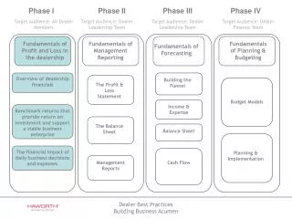
This document outlines the configuration and placement of thermal sensors, thermal couples, and strain gauges across multiple phases of an engineering project. Phase I presents an outer and inner view with specific angles and dimensions to ensure precise measurement and analysis. Phase II details the location of sensors on the outer and inner skin surfaces, including significant temperature variations and the use of gauges for monitoring structural integrity. Accurate information on sensor types, placement, and testing conditions is crucial for effective data collection in this multi-phase study.


PHASE I
E N D
Presentation Transcript
OUTER VIEW 0.075 inch S08 S08 (T) 45° Hoop 0° -20° 20° 3.00 Axial S10 S10 (T) 0.075 inch INNER VIEW IS24 INS2 N1 (T) IS25
0.075 inch S11 (T) S11 -20° 20° 45° S13 S13 (T) 0.075 inch
Temperature sensor, Thermal Couple and Strain Gages Locations 45° 45° 45° OUTER SKIN SURFACE INNER SKIN SURFACE 0.75 TC2 S08 4.76 4.76 4.76 IS24 1.0” (TYP) IS25 TSENSOR2 S10 TSENSOR TC1 0.75” Max S10 S08 IS32 IS27 IS24 IS25 IS26 INS2 Crack