GEANT MODELING AND COMPARISON WITH SOLIDWORKS MODEL
470 likes | 593 Vues
This presentation outlines the AgML implementation and modeling details of the PIXEL detector, including the Middle Support Cylinder (MSC) and beam pipe. It compares the dimensions and radiation lengths derived from GEANT and SolidWorks models, shedding light on geometry implementation and naming conventions. The talk emphasizes the transition from outdated technologies to a unified geometry model using AgML and addresses how this integration enhances simulation and reconstruction efficiency. The discussion includes material budget estimations and the significance of detailed geometric specifications.

GEANT MODELING AND COMPARISON WITH SOLIDWORKS MODEL
E N D
Presentation Transcript
GEANT MODELING AND COMPARISON WITH SOLIDWORKS MODEL PIXEL MATERIAL REVIEW Jonathan Bouchet
outline Overview of the AgML implementation of the PIXEL detector (PXL), Middle Support Cylinder (MSC) and beam pipe. • Beam Pipe : • Comparison with BrushwellMann drawing. • Radiation length, dimensions. • PXL and MSC : • Comparison of SolidWorks model (SW) and GEANT modeling : • The details of implementation (naming, dimensions of volumes). • Check of radiation length. Disclaimer : this talk only covers the details of the geometry implementation ; STAR-software (reconstruction, etc..) issues are addressed in the next talk. PIXEL MATERIAL REVIEW
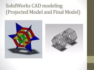
SW model of the PXL+MSC Pixel Support Tube (PST) PIXEL MATERIAL REVIEW Pixel Insertion Tube (PIT) Middle Support Cylinder = PST + PIT
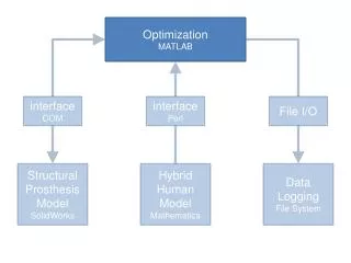
AgML : Abstract geometry Model Language (*) • STAR geometry is implemented in the Advanced Geant Interface (using GEANT3) : • Mortran pre-processor. • Several source codes are used for 1) simulation 2) conversion to TGeo (reconstruction) 3) conversion to Sti (tracking). • Sti cannot handle complex shapes. • No path forward to GEANT4, … • Change to AgML will allow : • Use of better simulation packages (GEANT4). • Unified geometry model : no differences in simulation, reconstruction and tracking. • Remove dependence on Jurassic technologies such as Mortran and ZEBRA. PIXEL MATERIAL REVIEW (*) J. Webb : -Collaboration Meeting, tracking review -STAR upgrade workshop
Representation of radiation length • Estimation of material budget for geometry dev13 [AgML]. • Use of the existing command line in STARSIM to plot the material for a given window η,φ, Rmin, Rmax. • Use of StarBASE (*) code plot radiation length vs.η,φ : • Parameters :η,φ ranges, binning , as well as the number of triggers per bins can be set up : more handy than the STARSIM command. • It plots the radiation length for a given GEANT volume, not by choosing the [Rmin,Rmax] range from the STARSIM command. • Both methods use 10GeV geantinos. PIXEL MATERIAL REVIEW (*) : http://drupal.star.bnl.gov/STAR/blog/jwebb/2010/feb/11/ howto-generate-geometry-material-differential-plots-using-starbase
1.New Beam Pipe Vertices : 30cm (blue) 0.cm (green) -30.cm (black) PIXEL MATERIAL REVIEW • The input was the Brushwellman drawing. • Coded as 3 sections of aluminum (edges) and beryllium (central part). • For |η|<1, the estimated radiation length is ~ 0.2-0.3 % X0 Figure3 : “Effective Thickness of the HFT Beam Pipe,. Beavis, August 26, 2009” *Beam pipe has been coded by Amilkar Quintero
Dimensions of the beam pipe PIXEL MATERIAL REVIEW Note : the length of the flanges is arbitrary because it was not specified in the drawing.
Radiation length of the beam pipe For |η|<6 PIXEL MATERIAL REVIEW For |η|<1
Radiation length of the beam pipe PIXEL MATERIAL REVIEW • The dimensions (length, radii) are agree with the Brushwellman drawing. • As seen in previous slide, there is more material budget for large Z : • in the central region where the pixel stands, the radiation is very low.
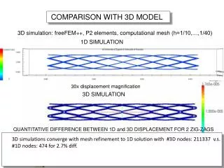
Comparison of the radiation length ~3-4.10-2 X0 ~3.5%X0 PIXEL MATERIAL REVIEW • The ordering of the radiation length profile vs. vertices positions is OK but the eta values of the change in profile are not completely agree • Compatibility of both simulations ?
Comparison between methods used to plot the radiation length STARSIM StarBASE PIXEL MATERIAL REVIEW • The radiation length vs. η(top) and φ (bottom ) shows the SAME profile for both methods.
2.PXL (SW) PIXEL MATERIAL REVIEW • The input for the PIXEL (ladder + sector) dimensions/shapes is the SW representation. • Flemming has done a translation of SW model to TGeo geometry. • It provides directly the shape, dimensions of the elements and then simplifies their implementation in AgML. • The idea was to code 1 sector and then duplicate it x10
1st iteration : Sector Support + active silicon • This is the first version (in CVS since december) of the PXL in AgML. • Volume naming convention. • PLAC = active silicon ladder : it was the name used in UPGR15. • PXCA-PXCB-PXCC-PXCD,PXCE • PXCF,PXGH,PXCH are the corners, starting from the bottom right () : • PiXel Corner A … • PXTR-PXTM-PXTL are the • planes supporting the active silicon • on the top : • PiXel Top Right , PiXel Top Middle, • PiXel Top Left. • PXTJ are the 2 planes joining the planes on the top : • PiXel Top Join • PXLB, PXRB, PXIB are the planes on front of the beam pipe and between 2 sectors (Pixel Low Beam, Pixel Rear Beam , Pixel Inner Beam). PIXEL MATERIAL REVIEW ()
PXTR PXTM PLAC PXTJ PXRB PXTL PIXEL MATERIAL REVIEW PXLB PXIB
plane PIXEL MATERIAL REVIEW arc
PXCC PXCD PXCE PXCB PXCF PXCG PIXEL MATERIAL REVIEW PXCA PXCH
2nd iteration : fine details of a Ladder thickness PLAC : active silicon r/phi dimension PIXEL MATERIAL REVIEW SIFL SIFR: passive silicon
All layers together GLUC: glue (adhesive) CFBK : Carbon Fiber BacKing thickness PIXEL MATERIAL REVIEW r/phi dimension GLUA, GLUB: glue (adhesive) ALCA : Aluminum Cable
PIXEL MATERIAL REVIEW Layer of active silicon Layer of passive silicon
Summary of material budget PIXEL MATERIAL REVIEW (*):forced Calculated by GEANT
Overview of the PIXEL PIXEL MATERIAL REVIEW
PIXEL DETECTOR radiation length For |η|<3 PIXEL MATERIAL REVIEW For |η|<1
PIXEL DETECTOR radiation length , for |eta|<.5 PIXEL MATERIAL REVIEW • Peaks in the azimuthal profiles comes from tracks crossing the entire pixel support. • Other small peaks are the overlaps between ladder.
SILICON SENSITIVE radiation length PIXEL MATERIAL REVIEW • For 1 layer of active silicon, the expected radiation length is 0.0677% (see slide 40). • then for 2 ladders (inner and outer), the radiation length should be : 0.1354%
3.1 SW model of the PST PIXEL MATERIAL REVIEW
3.2 SW model of the PIT PIXEL MATERIAL REVIEW
Example of implementation LFBA : Left Flange Base part A LFBB : Left Flange Base part B PIXEL MATERIAL REVIEW LFBK : Left FlangeBacKer APTS : APipe Tube Shell Length(Z) = 25mm Outer1 = 239 mm Inner1 = 237 mm Length(Z) = 1mm Outer2 = 259mm Inner2 = 239mm Length(Z) = 6mm Outer = 259mm Inner = 239 mm
Example of Naming convention : beam pipe support cone RFBA : Right Flange Base part A RFBB : RightFlange Base part B RFBK : Right Flange BacKer ABPR: ABeam Pipe Ring PIXEL material review BPPC : Beam Pipe PolyCon EBPP : End Beam Pipe Polycon RBPP : Ring Beam Pipe Polycon
Example of Naming convention : MSC transition plate MTPA : Msc Transition Plate part A MTPB : Msc Transition Plate part B MTPC : Msc Transition Plate part C MTPD : Msc Transition Plate part D PIXEL MATERIAL REVIEW MTPE : Msc Transition Plate part E 29
Overview of the MSC rails Rings surroundings the beam pipe PIXEL MATERIAL REVIEW • : temporary until • implementation of • real material (slide 39)
AgML model FGT PIXEL PST PIT PIXEL MATERIAL REVIEW SW model Note : in this version, the inner radii of the IDSM () has been changed from the coded value in order to avoid overlap with the PIT.
GEANT Volumes : Hierarchy PIXEL MATERIAL REVIEW • Volumes have to be organized by level in order for GEANT to find energy loss, impact point in each volumes/layers. • The current status is : • The IDSM includes the PIXEL and MSC. Issue : the MSC has a larger Z extension than the IDSM. • The beam pipe is at the same level of the IDSM. • The IDSM does not include the beam pipe. Issue 1 : the beam pipe has a larger extension in Z than the IDSM. Issue 2 : the beam pipe is inside the PIXEL, therefore it should be placed INSIDE the PIXEL/IDSM. • The MSC is placed with respect the center of the IDSM. • It is then placed at the center of STAR. • The pixel detector is not placed at the center of the IDSM because the active silicon are not symmetric along a ladder. • there’s a offset of the whole sector in order to have the center of the active silicon placed at (0,0,0).
CAVE IDSM PIPE All the other detectors Pixel : main volume Pixel : MSC FGT PSTM PXMO FGTM Sector : main volume PXLA_1 PXLA_3 PXLA_10 … PIXEL MATERIAL REVIEW LADR_3 LADR_4 LADR_2 LADR_1 … PLAC_1 SIFR SIFL Ladder : main volume
Radiation length breakdown PIXEL MATERIAL REVIEW • Left : using StarBASE ; it does not include the beam pipe material. • Right : using STARSIM ; it does include all material (beam pipe + PXL + FGT + IDSM) in |eta|<3 • There is more material (red histogram) for the PXL in eta<0 (Z<0) because the silicon ladder is asymmetric with respect the ladder support.
summary • PIXEL detector geometry has been implemented in AgML. • It has the fine details inherent to the PIXEL/CMOS sensor and then necessary for tracking evaluation. • The support material of the PIXEL, as well as the new beam pipe (requirement) have also been implemented. • Material, radiation length and dimensions look agree with the input source (SW, Brushwellman drawing). PIXEL MATERIAL REVIEW
Next steps • Refine material budget for the MSC (slide 39) • Remaining “big” parts of the MSC and some corrections : • Representation of ladder’s cables (slide 38) • Look at the GEANT tree for optimization. PIXEL MATERIAL REVIEW shrouds
end PIXEL MATERIAL REVIEW
Cables on a ladder PIXEL MATERIAL REVIEW
Material for some parts of the MSC PIXEL MATERIAL REVIEW From Joe Silber
IDS envelope/Interface drawing PIXEL MATERIAL REVIEW PST PIT
Radiation length vs η for IDSM, PIXEL, FGT • Default parameters are : • Ntrig = 4 • dφ =.2 • dη = .1 • |η|<6 • |φ|<1 deg. PIXEL MATERIAL REVIEW • Same with Ntrig =100 • Increasing the # of triggers give a slightly better resolution
Explanation of the “radlen vs. Z/eta” profile Real length of material crossed by the particle Z=0 PIXEL MATERIAL REVIEW Real length of material crossed by the particle Z≠0
Si 2 mil (0.0529%) 0.0677% sensor acrylic 2 mil (0.0148%) Al 0.7 mil (0.0124%) Al 0.7 mil (0.0124%) kapton 1mil (0.0073%) kapton 1mil (0.0073%) Al 0.7 mil (0.0124%) Al 0.7 mil (0.0124%) 0.079% 0.223 mm acrylic 2 mil (0.0148%) cable acrylic 2 mil (0.0148%) 10 mil carbon composite open weave (0.0587%) PIXEL MATERIAL REVIEW backer 0.2221% 4 mil silicon adhesive (0.0469%) 9.6 mil carbon composite sector beam (0.1017%) support beam TOTAL = 0.3688 % X0
Check with the [SSD] volume ACTIVE SILICON RDO SSD LADDERS ALL “SSD” PIXEL MATERIAL REVIEW
MTD EMC barrel MRPC ToF barrel 100% ready for run 10 (now!) EMC End Cap FMS BBC FPD TPC FHC PMD DAQ1000 Completed HLT Ongoing R&D HFT FGT HFT SSD IST PXL PIXEL MATERIAL REVIEW This review is focused on the PXL and its support structure
Radiation length of the beam pipe (starbase) PIXEL MATERIAL REVIEW • At mid rapidity (|η|<1), theradiation length is ~ 0.25%X0
PIXEL DETECTOR [PXMO volume] radiation length PIXEL MATERIAL REVIEW • right : radiation length vs. azimuth. • We observe double peaks (high radiation length) for tracks crossing the entire sector support • Other small peaks are the overlaps between ladder.