Download

1 / 20
200 likes | 339 Vues
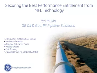
Securing the Best Performance Entitlement from MFL Technology. Ian Mullin GE Oil & Gas, PII Pipeline Solutions. Introduction to Magnetiser Design Mechanical Review Required Saturation Fields Velocity Effects Pole Spacing Magnetiser Bar vs. Solid Body Bristle.

E N D
Securing the Best Performance Entitlement from MFL Technology Ian Mullin GE Oil & Gas, PII Pipeline Solutions • Introduction to Magnetiser Design • Mechanical Review • Required Saturation Fields • Velocity Effects • Pole Spacing • Magnetiser Bar vs. Solid Body Bristle
Fundamental Magnetiser Designs Magnetiser Bar Solid Body Bristle
Mechanical Review • Solid Core Bristle Design / “Sweep’s Brush” • Simple and robust • Maintains good coupling with pipe-wall at all times • Bristles absorb the impact of in pipe obstacles • Sensors contact intrados/extrados of bends • Predictable drag forces • Compressibility limited by solid core and poles • Magnetiser Bar / “Magbar” Design • Possibility of extreme compressibility • Mechanically more complex design • Poles & sensors experience lift-off in bends • Large mass of magnetiser bar accelerated at pipeline obstacles • Large clamping forces Solid core bristle design is mechanically more robust and suitable for most pipeline environments. Magnetiser bar designs can be more suitable for multi-diameter lines if compromises are made elsewhere.
Magbar Issues with Bend Inspection [Extrados] Discrimination Sensors [Intrados] 3 of 4 external defects (20mm x 40%) visible. No signal from defect on bend extrados Main Corrosion Sensors SWEEP’S BRUSH MAGNETIZER BAR POF are now considering including bend inspection performance in their required specification
Required Saturation Field Levels Saturation - That degree of magnetization where a further increase in magnetization force produces no significant increase in the magnetic flux density (permeability) in a specimen.† • - Same vehicle used in half/full magnet build • Same EXTERNAL defect detected and sized • Same run speed • Defect sized exactly the same • Operating below the ‘knee’ of the curve • Sensitive to material variation, stress/strain etc. • Poor defect detection & sizing • Above the ‘knee’ • Pipe-steel is in saturation • Sensitive only to metal loss and wall thickness variation There are several sources of noise during inspection (magnetic, sensor, dynamics, electronics) and all of these must be addressed in order to obtain the best signal to noise ratios. Designing solely to achieve the highest fields possible will result in a sub-optimal design. † ASTM, “Standard Terminology of Symbols and Definitions Relating to Magnetic Testing”
Eddy currents • Faraday’s Law • Changing magnetic flux dB/dt induces electric current in conductor • Lenz’s law • Current generated by changing magnetic field will produce a magnetic field in opposition to that which generated it (induced field). ε= EMF J = Current Density σ = Electrical Conductivity Regions of high current density, J • Result of pig moving through pipeline: • Eddy currents generated in pipe (good electrical conductor) predominantly at points of pole contact • Opposing induced fields attenuate field levels across the pipe-wall • Field is concentrated onto inner pipe-wall
Velocity Effects • Axial field (-Hz) contour plot for pipe section between poles • Low velocity (<2m/s): • Axial field profile demonstrates good uniformity across wall thickness and axially across the sensor position • High field levels at sensor position throughout the wall thickness • With increasing velocity: • Axial fields attenuated across wall thickness • Field levels drop on outer wall • High fields migrate further toward rear bristle stack on inner wall
Pole Spacing Axial field levels measured 90% into pipe-wall (OUTER) • Short Pole-Spacing • Poor performance across speed range (0-5m/s) • Very sensitive to sensor positioning – vibration of sensor during inspection will produce noise on data • Little room for sensor positioning • Very high fields possible at low velocity • Long Pole-Spacing • Field levels lower than short pole-spacing design • Maintains field levels from 0-5m/s • Relatively insensitive to sensor positioning –hence also less noise due to sensor vibration • More room for optimal positioning of sensor Pole Spacing
Inner/Outer Pipe-wall Fields Direction of Motion Short pole-spacing 110mm Long pole-spacing 230mm • Field levels are predominantly much higher on the inner pipe-wall • Ideally the sensor should be placed in or around thecrossover point (red circles) • Short pole-spacing • - optimum sensor positioning possible? • large field gradients • inner wall field levels can be over 2x outer wall • Long pole-spacing • room for optimum sensor positioning • smaller field gradients • inner wall field levels can still be over 2x outer wall When field levels are quoted for performance comparison it is crucial that they are OUTER wall levels, as these will be the minimum values (POF standards*). However, it is not possible to directly measure outer-wall fields on-board during an inspection run. *Pipeline Operators Forum, “Specifications and Requirements for Intelligent Pig Inspection of Pipelines”
Magbar vs. Sweeps Brush 12mm 0m/s (static) Sweeps Brush Magbar 5m/s
Magbar vs. Sweeps Brush 18mm 0m/s (static) Sweeps Brush Magbar 5m/s
Magbar vs. Sweeps Brush • Sweeps Brush • Median pole spacing (150mm) maintains field across full speed range in 12mm/18mm wall • In 22mm wall fields have collapsed beyond 3m/s • Shorter pole-spacing gives: • higher fields at low velocities • less speed stability • Longer pole-spacing gives: • lower peak fields • better speed stability • less ‘peaky’ field profiles • Magbar • Median pole spacing (110mm) shows poor speed stability but high fields at low velocity • Shorter pole spacing gives: • higher fields at low velocities • variations in pole spacing has little influence on speed performance • Longer pole-spacing gives: • lower peak fields • some improvement in speed stability
Magnetiser & Sensor Lift-off Axial distance along pipe Axial distance along pipe Negligible drop in pipe-wall field at sensor position Sensor will not measure drop ~15% drop in pipe-wall field
Magnetics Review • Solid Core Bristle Design / “Sweep’s Brush” • - Suits long pole-spacing • Speed stable magnetic performance • Low sensitivity to lift-off • Uniform field profiles • Lower peak field levels at low velocity relative to magbar • - Good in realistic pipeline environment across a range of speeds • Magnetiser Bar / “Magbar” Design • - Suits shorter pole spacing • High peak field levels at low velocity • Poor magnetic performance at high speed • Sensitive to speed variations • ‘Peaky’ field profiles • - Good in ideal environment at low controlled speed
Thank you for listening Questions?